JoVE Science Education
Mechanical Engineering
This content is Free Access.
JoVE Science Education Mechanical Engineering
Hydraulic Jumps
  • 00:07Overview
  • 01:05Principles of Hydraulic Jumps
  • 03:57Preparing the Experiment
  • 04:55Data Collection
  • 06:00Analysis and Results
  • 07:59Applications
  • 08:48Summary

קפיצות הידראוליות

English

Share

Overview

מקור: אלכסנדר ס. רטנר ומהדי נביל; המחלקה להנדסה מכנית וגרעינית, אוניברסיטת מדינת פנסילבניה, פארק האוניברסיטאות, PA

כאשר נוזל זורם לאורך ערוץ פתוח במהירות גבוהה, הזרימה יכולה להיות לא יציבה, והפרעות קלות יכולות לגרום למשטח העליון הנוזלי לעבור בפתאומיות לרמה גבוהה יותר (איור 1a). עלייה חדה זו ברמת הנוזל נקראת קפיצה הידראולית. העלייה ברמת הנוזל גורמת לירידה במהירות הזרימה הממוצעת. כתוצאה מכך, אנרגיה קינטית נוזלית הרסנית מתפוגגת כחום. קפיצות הידראוליות מתוכננות בכוונה לעבודות מים גדולות, כגון דליפת סכרים, כדי למנוע נזק ולהפחית את הסחף שעלול להיגרם על ידי נחלים נעים במהירות. קפיצות הידראוליות מתרחשות באופן טבעי גם בנהרות ובנחלים, וניתן לראותן בתנאי הבית, כגון זרימה רדיאלית של מים מברז לכיור (איור 1ב).

בפרויקט זה יוקם מתקן ניסויי לזרימה פתוחה. שער ברד יותקן, שהוא שער אנכי שניתן להעלות או להוריד כדי לשלוט בקצב הפריקה של מים ממאגר במעלה הזרם לשפוך במורד הזרם. קצב הזרימה הנדרש לייצור קפיצות הידראוליות בשקע השער יימדד. ממצאים אלה יושוו לערכים תיאורטיים המבוססים על ניתוחי מסה ותנופה.

Figure 1
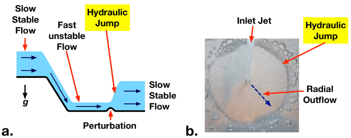
איור 1: א. קפיצה הידראולית המתרחשת במורד הזרם מתעלת זרימה עקב בעיה קלה לזרימה לא יציבה במהירות גבוהה. b. דוגמה לקפיצה הידראולית בזרימת מים רדיאלית מברז ביתי.

Principles

בזרימות רחבות של ערוצים פתוחים, הנוזל מוגבל רק על ידי גבול מוצק תחתון והמשטח העליון שלו חשוף לאטמוספירה. ניתוח נפח בקרה יכול להתבצע על קטע של זרימת ערוץ פתוח כדי לאזן את ההובלה פנימה והשקע של מסה ותנופה (איור 2). אם המהירויות הן הניח אחיד בפרצון ושקע של נפח הבקרה (V1 ו- V2 בהתאמה) עם עומקים נוזליים מתאימים H1 ו- H2,אז מאזן זרימת מסה יציב מפחית ל:

Equation 1 (1)

ניתוח התנע של x-כיווןשל נפח בקרה זה מאזן כוחות מלחץ הידרוסטטי (עקב עומק נוזלים) עם קצבי זרימת התנופה של המפרצון והשקע (Eqn. 2). כוחות הלחץ פועלים פנימה בשני צידי נפח הבקרה, והם שווים לכוח המשיכה הספציפי של הנוזל (צפיפות נוזל כפול תאוצה כבידתית: ρg),כפול העומק הנוזלי הממוצע בכל צד(H1 /2, H2/2), הכפיל את הגובה שעליו פועל הלחץ בכל צד (H1, ח2). התוצאה היא הביטוי הריבועי בצד שמאל של אקן. 2. קצבי זרימת התנע בכל צד (Eqn. 2, צד ימין) שווים לקצבי זרימת המסה של הנוזל דרך נפח הבקרה (ב: Equation 2 , out: Equation 3 ) מוכפל על ידי מהירויות הנוזל (V1, V2).

Equation 4 (2)

Eqn. 1 ניתן להחליף לתוך Eqn. 2 כדי לחסל V2. ניתן להחליף גם את מספר Equation 5 פרוד, המייצג את הכוח היחסי של תנופת נוזל הזרימה לכוחות הידרוסטטיים. ניתן לציין את הביטוי המתקבל כ:

Equation 6 (3)

למשוואה המעוקבת הזו יש שלושה פתרונות. אחד מהם הוא H1 = H2, המעניק את התנהגות הערוץ הפתוח הרגילה (עומק אינלט = עומק שקע). פתרון שני נותן רמה נוזלית שלילית, שהיא לא פיזיקלית, וניתן לבטל אותה. הפתרון הנותר מאפשר עלייה לעומק (קפיצה הידראולית) או ירידה לעומק (דיכאון הידראולי), בהתאם למספר פרוד המפרצון. אם מספר פרויד המפרצון (Fr 1 ) גדול מאחד, הזרימה נקראת סופר-ביקורתית (לא יציבה) ויש לה אנרגיה מכנית גבוהה(אנרגיהפוטנציאלית קינטית + כבידתית). במקרה זה, קפיצה הידראולית יכולה להיווצר באופן ספונטני או עקב הפרעה כלשהי לזרימה. הקפיצה ההידראולית מתפזרת אנרגיה מכנית לחום, מפחיתה באופן משמעותי את האנרגיה הקינטית ומגבירה מעט את האנרגיה הפוטנציאלית של הזרימה. גובה השקע המתקבל ניתן ע”י אק”ן 4 (פתרון לקצא’ם 3). דיכאון הידראולי לא יכול להתרחש אם Fr1 > 1 כי זה יגביר את האנרגיה המכנית של הזרימה, תוך הפרה של החוק השני של התרמודינמיקה.

Equation 7 (4)

כוח הקפיצות ההידראוליות גדל עם מספרי פרוד. ככל שפר 1 גדל, גודלו של H2/H1 עולה וחלק גדול יותר שלאנרגיה קינטית אינלט מתפוגג כחום [1].

Figure 2
איור 2: שלוט בעוצמת הקול של מקטע בזרימת ערוץ פתוח המכיל קפיצה הידראולית. קצבי זרימה של מסה ותנופה של זרימה של זרימה ליחידה מצוינים. כוחות הידרוסטטיים לכל רוחב יחידה המצוין בתרשים נמוך יותר.

Procedure

הערה: ניסוי זה משתמש במשאבה צוללת חזקה יחסית. המשאבה צריכה להיות מחוברת לשקע GFCI רק כדי למזער סיכונים חשמליים. ודא שאין התקנים אחרים המופעלים באמצעות מיזוג אוויר הפועלים בסמוך לניסוי. 1. ייצור מתקן זרימה ומיכל פתוחים (ראו תרשים וצילום, איור 3) אורכים חתוכים בעובי של כ-6.0 מ”מ × יריעת אקריליק בהירה ברוחב 9.5 ס”מ באורכים הבאים: 2×15 ס”מ, 2×25 ס”מ, 1×34 ס”מ, 1×41 ס”מ (איור 3a). מומלץ להשתמש במסור שולחן או בחותך לייזר כדי להבטיח שהקצוות שטוחים יחסית ולסדינים יש עובי שווה. חותכים חורים בפינות הימניות התחתונות של שתי יריעות אקריל 60 × 45 ס”מ להרכבה במד הזרימה (איור 3א). לחתוך חור בצד הימני העליון של הסדין הקדמי כדי להתקין את שסתום בקרת הזרימה. השתמש במלט אקריליק(למשל,SCIGRIP 16) כדי לקשר את לוחות האקריליק כפי שצוין בתאנה. 3a. יש להקפיד על אוורור נאות וללבוש כפפות בעת הטיפול במלט האקריליק. זה מועיל ליישם מלט עם מזרק מחט ולהשתמש סרט מיסוך כדי למקם לוחות במהלך הריפוי. אפשר למלט לרפא במשך 24 – 48 שעות. התקן את מד הזרימה בלוח הקדמי והדבק עם הברגים שסופקו. התקן אביזרי הפחתת NPT עד 1/2 NPT 1 ביציאות הכניסה והשקע של מד הזרימה. התקן 1/2 NPT עד 0.5 אינץ’. מתאמי תיל בקוטר פנימי לאביזריות אלה. התקן 0.5 ב. תעודת זהות ו-0.75 ב. זיהוי תיל מתאים על שסתום השער (בקרת קצב זרימה). חבר את התאמת התיל למשאבה הצוללת עם אורך ~ 20 ס”מ של צינורות, כך ידית שסתום קווים עם החור בצד ימין העליון של מארז אקריליק (איור 3b-c). הכנס את המשאבה למאגר התחתון, והתקן את השסתום כך שגזע השסתום יעבור דרך חור ההרכבה והידית נמצאת מחוץ למתחם (איור 3c). הכנס לוח אקרילי אנכי ליד החלק הכניסה של מתקן הזרימה, כך שיש כ 5.0 מ”מ פתח מתחתיו (איור 3b-c). רכיב זה ישמש כשער הסכר, וניתן להעלות ולהוריד אותו כדי לשלוט בזרימה מהמאגר העליון לערוץ. מלאו את המאגר העליון באופן רופף עם כרית סורק צמר נירוסטה. זה עוזר להפיץ זרימת מים נכנס באופן שווה על פני התעלה. חבר את שקע השסתום למפרצון מד הזרימה עם אורך של צינורות פלסטיק רכים. חבר את שקע מד הזרימה למאגר העליון עם צינורות פלסטיק. ודא כי צינור הצינורות למאגר העליון מעוגן היטב, כך שהוא לא להתנדנד החוצה כאשר המשאבה מופעלת. ממלאים את המאגר התחתון במים. 2. ביצוע ניסוי מדוד את גובה הרווח מתחת לשער באמצעות סרגל וציין את הערך כ- H1. הפעל את המשאבה, ולהתאים את קצב הזרימה באמצעות השסתום לשיעורי זרימה שונים (5 – 15 l min-1). השתמש בסרגל כדי למדוד את העומק הנוזלי במורד הזרם מהשער (H2) עבור כל מקרה. התבוננות איכותית בצורות הקפיצות ההידראוליות שנוצרות בקצבי זרימה שונים. שים לב לקצב זרימת הסף המינימלי להיווצרות קפיצה הידראולית. משרעת חדה יותר, גדולה יותר (H2 -H1), קפיצות צריכות להתרחש בקצבי זרימה גבוהים יותר. 3. ניתוח נתונים עבור כל מקרה קצב זרימה, חשב את מהירות המפרצון, V1, מקצב זרימת נפח. כאשר קצב זרימת עוצמת הקול ו- W הוא רוחב הערוץ. הערך את מספר פרויד ( ) ואת העומק הנוזלי התיאורטי במורד הזרם עבור כל מקרה (Eqn. 4). השווה ערכים אלה עם מעמקי קפיצה במורד הזרם. איור 3: א. תרשים סכמטי וממדים של מבנה המתקן.b. תרשים זרימה של מתקן קפיצה הידראולי.c. תמונה מסומנת של מתקן ניסוי.

Results

Upstream Froude numbers (Fr1) and measured and theoretical downstream depths are summarized in Table 1. The measured threshold inlet flow rate for formation of a hydraulic jump corresponds to Fr1 = 0.9 ± 0.3, which matches the theoretical value of 1. At supercritical flow rates (Fr1 > 1) predicted downstream depths match theoretical values (Eqn. 4) within experimental uncertainty.

Table 1 – Measured upstream Froude numbers (Fr1) and downstream liquid depths for H1 = 5 ± 1 mm

Liquid Flow Rate

(Equation 9, l min-1)

Upstream Froude Number (Fr1) Measured Downstream Depth (H2) Predicted Downstream Depth (H2) Notes
6.0   ± 0.5 0.9 ± 0.3 5 ± 1 5 ± 1 Threshold Froude number for hydraulic jump
11.0 ± 0.5 1.7 ± 0.5 11 ± 1 10 ± 2
12.0 ± 0.5 1.9 ± 0.6 12 ± 1 11 ± 2
13.5 ± 0.5 2.1 ± 0.6 14 ± 1 13 ± 2

Photographs of the hydraulic jumps from the above cases are presented in Fig. 4. No jump is observed for Equation 9 = 6.0 l min-1 (Fr1 = 0.9). Jumps are observed for the two other cases with Fr1 > 1. A stronger, higher amplitude, jump is observed at the higher flow rate supercritical case.

Figure 4
Figure 4: Photograph of hydraulic jumps, showing critical condition (no jump, Fr1 = 0.9) and jumps at Fr1 = 1.9, 2.1.

Applications and Summary

This experiment demonstrated the phenomena of hydraulic jumps that form at supercritical conditions (Fr > 1) in open channel flows. An experimental facility was constructed to observe hydraulic jump phenomena at varying flow rates. Downstream liquid depths were measured and matched with theoretical predictions.

In this experiment, the maximum reported inlet Froude number was 2.1. The pump was rated to deliver significantly higher flow rates, but resistance in the flow meter limited measurable flow rates to ~14 l min-1. In future experiments, a pump with a greater head rating or a lower pressure drop flow meter may enable a broader range of studied conditions.

Hydraulic jumps are often engineered into hydraulic systems to dissipate fluid mechanical energy into heat. This reduces the potential for damage by high velocity liquid jetting from spillways. At high channel flow velocities, sediment can be lifted up from streambeds and fluidized. By reducing flow velocities, hydraulic jumps also reduce the potential for erosion and scouring around pilings. In water treatment plants, hydraulic jumps are sometimes used to induce mixing and aerate flow. The mixing performance and gas entrainment from hydraulic jumps can be observed qualitatively in this experiment.

For all of these applications, momentum analyses across hydraulic jumps, as discussed here, are key tools for predicting hydraulic system behavior. Similarly, scale model experiments such as those demonstrated in this project, can guide the design of open-channel flow geometries and hydraulic equipment for large-scale engineering applications.

References

  1. Cimbala, Y.A. Cengel, Fluid Mechanics Fundamentals and Applications, 3rd edition, McGraw-Hill, New York, NY, 2014.

Transcript

A hydraulic jump is a phenomenon that occurs in fast-moving open flows when the flow becomes unstable. When a jump occurs, the height of the liquid surface increases abruptly resulting in an increased depth and decreased average flow velocity downstream. An important side effect of this phenomenon is that much of the kinetic energy in the upstream flow is dissipated as heat. Although hydraulic jumps often arise naturally, such as in rivers or the flow into a household sink, they are also purposely engineered into large waterworks to minimize erosion, or increase mixing. This video will illustrate the principles behind hydraulic jumps in a straight channel and then demonstrate the phenomenon experimentally using a small-scale open channel flow facility. After analyzing the results, some applications of hydraulic jumps will be discussed.

Consider the flow in a wide, straight section of an open channel where a hydraulic jump occurs and construct a control volume on a sluice around the jump. If the flow velocity is uniform at the inlet and outlet, conservation of mass yields a simple relation between upstream and downstream fluid depths. Depth multiplied by velocity is constant. A second relation can be found by considering conservation of momentum. Mass transported across the input and output carries momentum with it equal to the corresponding mass flux multiplied by the flow velocity. Hydrostatic forces on the surface of the control volume also contribute to the momentum balance and must be included. These forces are equal to the average pressure on the surface multiplied by the area. At this point, it is useful to introduce the Froude number, a dimensionless quantity named after the English engineer and hydrodynamicist, William Froude. The Froude number characterizes the relative strength of fluid momentum to hydrostatic forces. Now, if the momentum relation is rewritten in terms of the Froude number, with the output velocity eliminated by substitution using the mass relation, the result is a cubic equation in terms of the ratio of downstream and upstream depths. This equation can be simplified by factoring out the trivial solution where the upstream and downstream depths are equal. The two remaining solutions are easily found using the quadratic equation, but the negative solution can be eliminated since it is non-physical. The remaining solution corresponds to an increase in depth, a hydraulic jump, or a decrease in depth, a hydraulic depression, based on the value of the upstream Froude number. If the upstream Froude number is greater than one, the flow has a high mechanical energy and is supercritical or unstable. A hydraulic depression cannot form in this regime because it would increase mechanical energy and violate the second law of thermodynamics. On the other hand, a hydraulic jump can form, either spontaneously or due to some disturbance in the flow. An input Froude number of one represents the minimum threshold for the onset of a hydraulic jump. Hydraulic jumps dissipate mechanical energy into heat, and significantly reduce the kinetic energy, while slightly increasing the potential energy of the flow. As the Froude number increases, so does the ratio of downstream to upstream depths and the amount of kinetic energy dissipated as heat. Now that we understand the principles behind hydraulic jumps, let’s examine them experimentally.

First, fabricate the open channel flow facility as described in the text. The facility has an upper and lower reservoir connected by an open channel. Water pumped from the lower reservoir is deposited in the upper reservoir with the flow rate controlled and measured by a valve and flow meter in line with the pump. Steel wool in the upper reservoir helps to evenly distribute the water across the width of the section, and the adjustable sluice gate controls the fluid depth as it enters the channel. After flowing through the channel, the fluid is deposited back into the lower reservoir. When the flow facility is assembled, set it up on a bench and remove any nearby electronic devices. Plug the pump into a GFCI outlet to minimize the risk of electrical shock, and then fill the lower reservoir with water. You are now ready to perform the experiment.

Adjust the sluice gate to approximately five millimeters. Measure the final height of the gap underneath the sluice gate using a ruler, and record this distance as the upstream flow depth, H1. When you are finished, turn on the pump and use the valve to maximize the flow rate without exceeding the scale on the flow meter. Use the ruler again to measure the fluid depth after the hydraulic jump. Record the flow rate, along with this second distance which is the downstream flow depth, H2. Before continuing, observe the shape of the hydraulic jump. You should notice larger, more abrupt transitions for higher flow rates, and smaller, more gradual transitions for lower flow rates. Now, repeat your measurements and observations for successively lower flow rates. Try to determine the minimum threshold flow rate for the formation of a hydraulic jump. Once you have found the threshold flow rate, you are ready to analyze the results.

For each volumetric flow rate, you should have a measurement of the downstream fluid depth. The upstream depth is the same for all cases. Complete the following calculations for each measurement and propagate uncertainties along the way. First, determine the inlet flow velocity. Divide the volumetric flow rate by the channel width and upstream depth. Next, evaluate the upstream Froude number using the definition given before, and substituting in the acceleration due to gravity, as well as the upstream height and velocity. Now, use the Froude number and the non-trivial solution for the jump height to calculate the theoretical downstream depth. Compare the theoretical prediction with the measured downstream depth. At supercritical flow rates, the predictions match the measured depths within experimental uncertainty. Look at your results for the threshold flow rate. Within experimental uncertainty, the Froude number is one, as we anticipated from the theoretical analysis. The rate of mechanical energy loss through the hydraulic jump can also be calculated from these data. First, calculate the mechanical energy of the fluid flowing into the jump, which is the sum of kinetic and potential energy flow rates at the inlet. Now, determine the output energy rate in the same way, but with values at the outlet. The rate of mechanical energy dissipation to heat is the difference between the input and output rates. In this experiment, the energy loss rate can reach about 40% of the inlet energy, or higher. These results highlight the effectiveness of momentum analyses and scale model experiments for understanding and predicting the behavior of hydraulic systems. Now let’s look at some other ways hydraulic jumps are utilized.

Hydraulic jumps are an important natural phenomenon with many engineering applications. Hydraulic jumps are often engineered into hydraulic systems to dissipate fluid mechanical energy into heat. This reduces the potential for damage by high velocity liquid jetting from spillways. At high channel flow velocities, sediment can be lifted up from streambeds and fluidized. By reducing flow velocities, hydraulic jumps also reduce the potential for erosion and scouring around pilings. In water treatment plants, hydraulic jumps are sometimes used to induce mixing and aerate flow. The mixing performance and gas entrainment from hydraulic jumps can be observed qualitatively in this experiment.

You’ve just watched JoVE’s introduction to hydraulic jumps. You should now understand how to use a control volume approach to predict the flow behavior, and how to measure this behavior using an open channel flow facility. You’ve also seen some practical uses for engineering hydraulic jumps in real applications. Thanks for watching.

Tags

Cite This
JoVE Science Education Database. JoVE Science Education. Hydraulic Jumps. JoVE, Cambridge, MA, (2023).