Overview
资料来源:佩曼·沙贝吉-鲁德波什蒂和西娜·沙赫巴兹莫哈马迪,康涅狄格大学生物医学工程系,康涅狄格州斯托尔斯
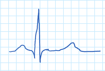
心电图是记录患者躯干电极之间发生电势变化以显示心脏活动的图形。心电图信号跟踪心脏节律和许多心脏疾病,如血液流向心脏和结构异常。心脏壁收缩产生的作用潜能会将来自心脏的电流扩散到全身。扩散电流在身体各点产生不同的电位,这些电位可以通过放置在皮肤上的电极来感应。电极是金属和盐制成的生物传感器。实际上,10个电极连接到身体上的不同点。有一个标准程序来获取和分析心电图信号。健康个体的典型心电图波如下:

图 1.心电图波。
"P"波对应于心房收缩,而"QRS"复杂对应于心室收缩。"QRS"复合体比"P"波大得多,因为心肌质量相对发泡,掩盖了心房的放松。心室的松弛可以以"T"波的形式看到。
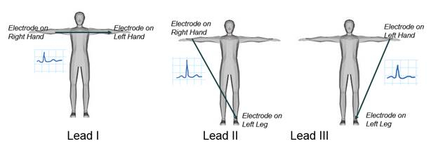
有三个主要引线负责测量手臂和腿之间的电势差,如图 2 所示。在此演示中,将检查其中一条肢体引线,引线 I,并记录两个臂之间的电势差。与所有 ECG 引线测量一样,连接到右腿的电极被视为接地节点。将使用生物电位放大器采集ECG信号,然后使用仪器软件显示,其中将创建增益控制以调整其振幅。最后,对记录的ECG进行分析。

图 2.心电图肢体引线。
Principles
心电图必须不仅能够检测 0.5 mV 到 5.0 mV 的极弱信号,而且检测出高达 ±300 mV 的直流分量(由电极-皮肤接触引起),以及高达 1.5 V 的共模分量,这是电位产生的电极和接地之间。ECG 信号的有用带宽取决于应用,范围为 0.5-100 Hz,有时可达 1 kHz。在外部高频噪声、50 或 60 Hz 干扰和直流电极偏移电位较大的情况下,一般在 1 mV 峰峰值附近。其他噪声源包括影响皮肤电极界面的运动、肌肉收缩或肌电图尖峰、呼吸(可能是有节奏或零星的)、电磁干扰 (EMI) 以及其他电子设备的噪音夫妇进入输入。
首先,将生产一个生物电位放大器来处理心电图。然后,电极将放置在患者身上,以测量两只手臂之间的电位差。生物电位放大器的主要功能是接收生物源的弱电信号,增加其振幅,以便进一步处理、记录或显示。

图 3.ECG放大器。
为了在生物学上有用,所有生物电位放大器必须满足某些基本要求:
- 它们必须具有高输入阻抗,以便它们提供被测信号的最小负载。生物电位电极可能受其负载影响,从而导致信号失真。
- 生物电位放大器的输入电路还必须为所研究的受试者提供保护。放大器应具有隔离和保护电路,以便通过电极电路的电流保持在安全水平。
- 输出电路驱动负载,通常是指示或记录设备。为了在读出中获得最大的保真度和范围,放大器必须具有低输出阻抗,并能够提供负载所需的功率。
- 生物电位放大器必须在其放大的生物电位存在的频谱中工作。由于此类信号的水平低,因此限制放大器的带宽以获得最佳信号到噪声比非常重要。 这可以使用筛选器来完成。
图 3 是 ECG 放大器的示例,图 4 是在此演示期间构建的 ECG 放大器电路。它有三个主要阶段:保护电路、仪表放大器和高通滤波器。

图 4.生物电位放大器。
第一阶段是患者保护电路。二极管是一种半导体器件,它向一个方向传导电流。当二极管向前偏置时,二极管充当短路并导电。当二极管反向偏置时,它充当开路不导电,ir = 0。
当二极管处于正向偏置配置中时,必须超过一种称为阈值电压(VT = 约 0.7 V)的电压,以便二极管传导电流。一旦超过 VT,无论V in 是什么,二极管上的压降都将在 VT 处保持不变。
当二极管反向偏置时,二极管将充当开路,并且二极管上的电压降将等于V in。
图 5 是一个基于此演示中使用的二极管的简单保护电路的示例。电阻器用于限制流经患者的电流。如果仪表放大器或二极管中的故障使患者与其中一个电源轨的连接短路,则电流将小于 0.11 mA。FDH333 低漏二极管用于保护仪表放大器的输入。当电路中的电压超过0.8 V的幅度时,二极管将改变其活动区域或"ON"状态;电流流经它们,保护患者和电子元件。

图 5.保护电路。
第二阶段是仪表放大器 IA,它使用三个运算放大器(运算放大器)。每个输入都附带一个运算放大器,以增加输入电阻。第三个运算放大器是差分放大器。此配置能够抑制接地参考的干扰,并且仅放大输入信号之间的差异。

图 6.仪表放大器。
第三阶段是高通滤波器,用于放大在大直流电压之上的小交流电压。心电图受来自患者运动和呼吸的低频信号的影响。高通滤波器可降低此噪声。
高通滤波器可以通过一阶RC电路实现。图 7 显示了一阶高通滤波器及其传输函数的示例。截止频率由以下公式给出:
 ,
,


图 7.高通滤波器。
Procedure
1. 获取心电图信号
- 将电源的电压调整到 +5 V 和 -5 V,并串联连接。
- 构建如图 4所示的电路。计算电阻和电容器的值。对于高通滤波器,截止频率应为 0.5 Hz。电容器值应从下表中选择(根据可用性)。
| 可用电容器值 (μF ) | ||
| 0.001 | 1 | 100 |
| 0.022 | 2.2 | 220 |
| 0.047 | 4.7 | 470 |
| 0.01 | 10 | 1000 |
| 0.1 | 47 | 2200 |

- 将电极放在患者的右臂、左臂和右腿(这是参考)上,并将其连接到电路。
- 使用示波器查看心电图信号 (Vo)。按"自动设置"并根据需要调整水平和垂直比例。您应该能够看到 R 峰值,尽管信号中有噪声。
2. 使用仪器软件显示心电图信号
- 在本演示中,我们使用 LabVIEW。编写一个程序,使用图形界面显示ECG信号,用于配置测量和波形图。选择模拟输入后,使用以下设置配置程序:
- 信号输入范围 >> 最大值 = 0.5;最小值 = -0.5
- 终端配置 >> RSE
- 采集模式 >> 连续
- 要阅读的样品 = 2000
- 采样率 = 1000
- 获取 ECG 信号并观察波形。您将看到类似于图 1的信号。
- 调整 x 轴的比例以显示时间(以秒为单位)。
- 仪器中通常有必要将感兴趣的信号放大到特定的振幅。创建增益控制并将其设置为 ECG 的振幅为 2 Vp。
3. 分析心电图信号
在本节中,将过滤和分析心电图信号以确定心率。下面的框图显示了程序的组件。
- 使用波形图显示信号。
- 使用振幅和相位谱子vi(在信号处理和光谱中)评估信号的频谱,并使用波形图显示其幅度。水平轴对应于频率。它是离散的,因为计算机使用快速傅立叶变换 (FFT) 算法来计算信号的频谱。频率从 k = 0 到 k = (N-1)/2,其中 N 是序列的长度,在本例中为 4000。要计算相应的模拟频率,请使用以下公式:

其中fs是采样频率。请注意,信号的大部分能量在低频范围内,并且在中频范围内存在高强度的峰值。使用上面提供的公式计算该峰值的频率。 - 使用切比舍夫函数的巴特沃斯实现低通滤波器。选择等于100赫兹的截止频率。确保滤波器在停止带中提供至少-60分贝/十年的衰减。
- 将从电子表格subvi 读取的输出信号连接到低通滤波器的输入。
- 使用巴特沃斯或切比舍夫函数实现停止带滤波器。目标是在不修改其他频率的情况下减少 60 Hz 干扰。尝试接近 60 Hz 的边框频率。
- 将低通滤波器的输出连接到止止区滤波器的输入。
- 使用峰值检测器子vi 查找峰值(位于信号处理和 Sig 操作中)。对于阈值,查看信号的振幅并选择最合适的值。
- 使用索引数组子维(在编程 + 数组中)提取峰值的位置。
- 从较高位置减去较低的位置,然后乘以采样周期 T = 1/fs 以获得 RR 间隔。
- 计算倒数和调整单位,并放置一个指标来显示 BPM。
心电图记录心脏活动,用于诊断疾病、检测异常和了解心脏整体功能。电信号是由心脏壁的收缩产生的,这些收缩驱动电流,并在整个身体产生不同的电位。通过在皮肤上放置电极,可以在心电图中检测并记录此电活动。ECG 是非侵入性的,使其成为评估患者心脏表现的有用工具,例如通过测量血液流向器官的能力。
本视频将说明 ECG 的主要部分,并演示如何使用生物电位放大器获取、处理和分析典型的 ECG 信号。还将讨论利用电信号处理诊断疾病的其他生物医学应用。
为了理解心电图的原理,让我们首先了解心脏是如何产生电信号的。对于正常、健康的心脏,在休息时,心电图会显示一系列反映心跳不同阶段的波。ECG 从中心节点开始,也称为 SA 节点,位于右中心中心,在心脏中充当心脏起搏器。电信号导致心房收缩,迫使血液进入心室。此序列记录为心电图上的 P 波。然后,这个信号从心室穿过心室,导致他们收缩并泵血到身体的其余部分。这将记录为 QRS 复合体。
最后,心室放松,这是记录为T波。然后,该过程重新开始,并针对每个检测信号重复。请注意,QRS 波比 P 波大得多,这是因为心室比心室大。这意味着它们掩盖了atria或T波的放松。身体的其他过程,如呼吸或肌肉收缩,可能会干扰心电图测量。用于获取它们的电路的电流也相同。通常,心电图试图记录的电信号相当微弱。因此,生物电位放大器用于增加其振幅,从而可以对其进行进一步处理和记录。
生物电位放大器、患者保护级、仪器放大器和高通滤波器有三个主要组件。如主要建议,患者保护电路使用电阻和二极管的组合来保护患者以及机器和设备。电阻器限制流经患者的电流,因为二极管保持电流向正确方向流动。
下一个阶段是仪表放大器,它放大了每个电极输入之间的差异。它由三个运算放大器组成。两个增加每个输入的电阻,第三个放大输入信号之间的差值。
最后一个阶段是高通滤波器,它减少噪声并过滤出患者运动或呼吸产生的低频信号。现在,您已经了解了 ECG 的测量方式,让我们看看如何构建生物电位放大器并处理数据以获得干净的 ECG 信号。
在回顾了心电图的主要原则后,让我们看看如何构建生物电位放大器并获取心电图信号。首先,首先收集一个原板、一个AD-620仪表放大器和所有必要的电路元件。然后,使用以下方程计算电路中所有电阻和电容器的值。
对于高通滤波器,切断频率应为0.5赫兹。
然后,插入电容器值以确定电阻。接下来,根据所提供的图构建一个生物电位放大器。下面是最终电路的外观。将三根带鳄鱼夹的导线连接到直流电源的接合柱上,然后打开电源。将电压调整到加 5 伏和负 5 伏,并将导线串联连接到电路。
现在,使用酒精准备垫擦拭患者右手腕、左手腕和右脚踝。在将导电胶胶添加到电极中,然后再将其放入患者身上。然后,使用带有鳄鱼夹的导线将电极连接到电路。打开示波器并获取心电图信号。根据需要调整水平和垂直比例。通过这些调整,您应该能够看到波形的 R 峰值。
将电路连接到 PXI 机箱,然后打开仪表软件,使用或编写显示 ECG 信号和波形图的程序。
使用以下设置配置数据采集接口。将 x 轴的比例标上以显示时间和秒,然后将 ECG 信号显示为波形。如果需要放大信号,请创建增益控制并设置它,以便 ECG 的振幅为两个 VP。
现在,我们已经演示了如何获取 ECG 信号,让我们看看如何分析结果。这是一个代表性的ECG信号。P、QRS 和 T 波几乎无法识别,因为它们被噪音和波动所遮蔽。此信号需要滤波。要转换此信号,首先在菜单上选择"信号处理",然后选择频谱。快速傅立叶变换算法计算并绘制信号频谱,在水平轴上以隐蔽值显示频率。信号中的大部分能量处于低频。
但是,在中频范围内有一个高强度的峰值,假定是噪声。频率在水平轴上绘制为 k,从零到 N 减去 1,其中 N 是序列的长度。对于此实验,N 等于 2,000。使用以下公式计算每个 k 值的模拟频率,其中 f s 是采样频率,并根据 FFT 图确定高强度峰值的频率。
然后,创建截止频率为 100 赫兹的低通滤波器。使用巴特沃斯或切比舍夫函数来过滤信号,信号在停止带中每十年至少衰减 60 分贝。将数据子 VI 的输出信号连接到低通滤波器的输入。此滤波器可去除 ECG 的无关高频波。现在,创建一个带停止滤波器,并将截止频率设置为大约 55 和 70 赫兹。
要移除嘈杂的信号,大约 60 赫兹。然后,将低通滤波器的输出连接到 Bandstop 滤波器的输入。尝试接近 60 赫兹的边框频率。这将减少干扰,而不会影响其他频率。ECG 信号现在应该是明确的,具有不同的 P、QRS 和 T 复合体。
现在,让我们使用过滤的心电图信号确定心率。首先,使用峰值检测器子 VI 查找信号的峰值。根据阈值的 R 波的信号振幅选择最合适的值。然后,使用索引数组子 VI 确定峰值的位置。
从较高位置减去较低的峰值位置,然后将此值乘以采样周期 T,T 等于 f s 以上。此值是两个 R 波之间的时间长度。调整单位以确定每分钟的节拍。
在本演示中,测得的心率约为每分钟 60 次。
心电图和信号处理在医学和研究方面都有重要的应用。除了非侵入性外,ECG 还相对便宜。使其成为医院的有用且易于访问的工具。ECG甚至可以适应对正在治疗急性冠状动脉综合征的患者进行更加复杂和长期的监测。
为此,使用12条心电图引线,可以识别无症状患者的瞬态心肌缺血。信号采样和处理也用于脑电图测量来自大脑的电信号。EEG 通常与功能 MRI 结合使用,作为多模态成像技术。
该方法无创地生成大脑活动皮质图,用于许多神经成像应用,例如视觉或运动激活后。
您刚刚观看了 Jove 关于获取和分析 ECG 信号的介绍。您现在应该了解如何产生 ECG 信号,以及如何创建生物电位放大器来检测弱电信号。您也看到信号处理在医学诊断中的一些生物医学应用。
谢谢你的收看。
Results
在本演示中,三个电极连接到单个电极,输出通过生物电位放大器。数字滤波前心电图示例如下(图8)。

图8.无数字滤波的 ECG 信号。
在设计过滤器并将数据馈送到开发的算法后,检测到图形上的峰值并用于计算心跳率 (BPM)。图 9在时间和频率域中显示原始数据(在任何滤波之前)的 ECG 信号。图 10显示了过滤该信号的结果。

图 9.滤波前的ECG信号。

图10.过滤心电图信号。
原始心电图图具有略微可见的 P、QRS 和 T 复合体,这些复合物从噪声中呈现了许多波动。ECG信号的频谱还显示了65赫兹的明显尖峰,这被认为是噪声。当使用低通滤波器处理信号以去除无关高频部分,然后使用带停止滤波器移除 65 Hz 信号分量时,输出看起来明显更清洁。ECG 在消除所有噪声后,清楚地显示信号的每个分量。
此外,测得的心率约为每分钟61.8609次。
Applications and Summary
心脏周期内心肌收缩在胸部内产生电流。电阻组织之间的电压下降由放置在皮肤上的电极检测,并由心电图记录。由于电压较弱,在0.5 mV范围内,与噪声量小,因此需要处理和过滤信号。本实验设计了一个由两部分模拟和数字信号处理电路组成的心电图装置,用于分析生成的ECG信号,并计算心跳速率。
本演示介绍了电子电路和ECG信号滤波的基本原理。在这里,实用的信号处理技术用于从噪声背景中提取弱信号。这些技术可用于需要信号放大和降噪的其他类似应用。
材料列表
| 名字 | 公司 | 目录号 | 评论 |
| 设备 | |||
| 电源 | 黑白精密度 | 1760A | |
| 万用表 | |||
| 示波器 | |||
| 原板 | |||
| 4 个 FDH333 二极管 | |||
| 1 AD620 | |||
| 3 47kΩ电阻器 | |||
| 2 个 100nF 电容器 | |||
| 3 ECG 电极 | |||
| 几个鳄鱼夹和泰克探测器。 |


