

Summary
The application of a classical fear conditioning behavioral paradigm for auditory prosthetic research in rats is described. This paradigm provides a mechanism for identifying both detection of, and discrimination between, distinct acoustic and electrical stimuli using heart-rate as an outcome measure.
Abstract
Acute animal preparations have been used in research prospectively investigating electrode designs and stimulation techniques for integration into neural auditory prostheses, such as auditory brainstem implants1-3 and auditory midbrain implants4,5. While acute experiments can give initial insight to the effectiveness of the implant, testing the chronically implanted and awake animals provides the advantage of examining the psychophysical properties of the sensations induced using implanted devices6,7.
Several techniques such as reward-based operant conditioning6-8, conditioned avoidance9-11, or classical fear conditioning12 have been used to provide behavioral confirmation of detection of a relevant stimulus attribute. Selection of a technique involves balancing aspects including time efficiency (often poor in reward-based approaches), the ability to test a plurality of stimulus attributes simultaneously (limited in conditioned avoidance), and measure reliability of repeated stimuli (a potential constraint when physiological measures are employed).
Here, a classical fear conditioning behavioral method is presented which may be used to simultaneously test both detection of a stimulus, and discrimination between two stimuli. Heart-rate is used as a measure of fear response, which reduces or eliminates the requirement for time-consuming video coding for freeze behaviour or other such measures (although such measures could be included to provide convergent evidence). Animals were conditioned using these techniques in three 2-hour conditioning sessions, each providing 48 stimulus trials. Subsequent 48-trial testing sessions were then used to test for detection of each stimulus in presented pairs, and test discrimination between the member stimuli of each pair.
This behavioral method is presented in the context of its utilisation in auditory prosthetic research. The implantation of electrocardiogram telemetry devices is shown. Subsequent implantation of brain electrodes into the Cochlear Nucleus, guided by the monitoring of neural responses to acoustic stimuli, and the fixation of the electrode into place for chronic use is likewise shown.
Protocol
1. Electrocardiogram Telemetry Device Implantation
- One hour prior to implantation surgery commencement, administer Carprofen (4 mg/kg s.c.) to provide post-operative analgesia.
- Inject Ketamine/Xylazine (Ke: 70 mg/kg, Xy: 10 mg/kg, i.p.) for anaesthesia to allow initial animal preparation including shaving and inserting ear bars before switching to Isoflurane anaesthesia which is more stable during surgery allowing better regulation of depth and shortens post-surgery recovery from anaesthesia.
- At anaesthesia onset, apply eye lubricant to the animal's eyes and then shave the abdomen thorax, and throat. Wipe the exposed skin using surgical scrub, followed by alcoholic skin preparation, followed by antiseptic solution. Place the home cage on an heat blanket to warm.
- Place the animal in the supine position on a homeothermic plate. Insert wadding underneath the neck to elevate and expose the throat.
- Place the nose-cone (delivering 1-3% vol/vol Isoflurane in oxygen, 2 L per min) over the nose of the animal and fix the cone in place.
- Fix the fore-limbs in a semi-extended position to generate skin tension over the thorax and throat, and to prevent the nose slipping free of the nose-cone.
- Insert the probe of the homeothermic blanket into the rectum of the animal.
- Make a midline incision in the skin extending from the xiphoid process 20 mm caudally to expose the muscle layer. Make a matching incision along the linea alba, and then the peritoneal cavity.
- Insert the ECG telemetry device into the peritoneal cavity with leads extending from the rostral end of the opening, and suture the caudal 15 mm of the opening in the peritoneum.
- Make a midline incision in throat overlying the trachea, exposing the sternohyoid muscle.
- Insert alligator ear forceps into the subcutaneous space of the rostral incision facing caudally, and use these to form a subcutaneous tunnel from the rostral to caudal incision. Grip the positive (red) lead in the forceps and retract the lead through the tunnel.
- Lift the sternohyoid muscle using forceps and insert the tip of the positive lead dorsally toward the right anterior mediastinum, leaving approximately a 1 mm loop of cable rostral to insertion. Suture the lead where it extends from the thoracic cavity and at the top of the loop to the underlying muscle.
- Expose the dorsal wall of the xiphoid, and suture the tip of the negative lead the exposed surface.
- Check the implanted device signal to ensure an adequate ECG can be obtained.
- Feed excess cable into the peritoneal cavity. Suture closed the peritoneal wall, the linea alba, and the abdominal skin.
- Suture closed the skin of the throat.
- Cease delivery of Isoflurane, and continue to deliver oxygen until spontaneous movement is observed.
- When movement is observed, release the forelimbs and return the animal to its home cage. Move the home cage so that approximately half the cage is on the heat pad. This will allow the animal, when mobile, to move between warmer and cooler areas of the cage. Monitor the animal until ambulatory, and leave the home cage on the heat blanket for 24 hours.
- Administer Carprofen (4 mg/kg s.c.) every 24 hours for 3-5 days.
2. Brain Electrode Implant
- One hour prior to implantation commencement, administer Carprofen (4 mg/kg s.c.) for post-operative analgesia.
- Inject Ketamine/Xylazine (Ke: 70 mg/kg, Xy: 10 mg/kg, i.p.) for anesthesia.
- At anaesthesia onset, apply eye ointment to protect the eyes, then shave the head of the animal. Wipe the exposed skin using betadine scrub, followed by alcohol, followed by betadine.
- Place the animal in the prone position on a homeothermic plate.
- Position one hollow ear bar in approximately the expected final position, and lift and position the animal so that the ear bar is located in the external acoustic meatus.
- Slide the second hollow ear bar into the contralateral external acoustic meatus.
- Using rat-tooth forceps, open the animal's jaw and hook the upper incisors over the tooth holder.
- Slide the nose-cone over the nose, and commence delivery of Isoflurane (1-3% vol/vol in oxygen). Animals are now maintained throughout surgery with this anaesthetic.
- Make an incision in the skin of the head, approximately 1 mm left of the midline and extending from 3-4 mm rostral to 2-3 mm caudal of lambda.
- Retract the skin and muscle laterally from the incision, exposing the parietal bone and the interparietal bone. Scrub the surface of the exposed bone using 20% hydrogen peroxide solution and a gauze pad.
- Drill a small hole in the left and right parietal bones, and screw a surgical steel screw into each hole leaving a small (0.5 mm) space between the head of each screw and the skill. Connect these screws to the ground and reference electrode points of the high-impedence headstage.
- Drill a hole approximately 2 mm square in the lateral-most extent of the interpariental bone. Flush the hole using sterile saline to remove any bone dust or bone fragments which may damage the electrode.
- Attach the coupling speaker to the left hollow ear bar.
- Using the tip of a needle, make an incision in the dura on the sagittal plane.
- Bring the electrode manipulator into place above the opening, with a caudorostral angle of 10 °. Insert the electrode manually approximately 2 mm into the surface of the brain. Ensure the amplifier is turned on, then seal the recording chamber.
- Commence cyclical delivery of low (2-8 kHz), mid-range (16-24 kHz) and high (32 kHz-44kHz) frequency band-pass filtered noise. The maximum rate at which bursts should be delivered is one burst every 200 ms. Monitor neural activity at each channel to detect responses to noise presentation.
- Continue insertion of the electrode until either total inserted distance is approaching 8 mm. If the 8 mm limit is reached without neural responses being detected, withdraw and reposition the electrode for another insertion. If the cochlear nucleus (CN) has been reached, sites at the tip of the electrode should be showing responses primarily to high-frequency stimuli. If electrodes are located in the ventral cochlear nucleus (VCN), responses to acoustic stimulus should have a strong onset component (1-5 ms), followed by a rapid decrease in activity.
- Continue to insert the electrode until the tips of the electrode detect responses to low-frequency stimuli, or auditory-driven activity ceases to occur (in which case, the electrode may have passed entirely through the CN and it may be necessary to revise the electrode placement).
- Construct a frequency-amplitude response map of the neurons at electrode sites. This is achieved by presented sound across the desired frequency range (typically 1-44 kHz or 1-80 kHz) at amplitudes 1-70 dB, with 10 repetitions of each stimulus. One stimulus may be delivered every 300 ms when mapping the CN. If the map is inadequate, consider revising the placement of the electrode.
- Apply a thin layer of silicon elastomer slightly above the exposed electrode shanks, such that the elastomer will flow down the shanks and coat both the shanks and the exposed surface of the brain.
- Apply a first layer of denture cement polymer around the electrode. The cement should be minimally viscous, to reduce the risk of the electrode being moved in the process of application. Ensure that the polymer does not cover the screws in the parietal bones or the attached cables. Wait for the acrylic to harden, which typically takes 5-10 minutes.
- Detach the ground and reference wires of the headstage from the screws in the parietal bones. Using forceps, gently wind the ground wire of the electrode around the screw in the left parietal bone.
- Apply a second layer of denture cement polymer. This second layer should encapsulate both screws, and flow into the space between the head of the screw and the skull. In doing so, the screws will hold the acrylic and electrode to the skull. Wait for the acrylic to harden.
- Remove the headstage from the electrode connector.
- Using rat tooth forceps, lift the skin lateral to the polymer over the polymer, and use a purse-string suture to close the skin around the exposed electrode connector.
- Remove the ear bars, releasing the head.
- End delivery of Isoflurane, and continue to deliver oxygen through the nose cone until spontaneous movement is observed.
- Return the animal to the home cage. Move the home cage so that approximately half the cage is on the heat pad. This will allow the animal, when mobile, to move between warmer and cooler areas of the cage.
- Monitor the animal until ambulatory. Leave the home cage on the heat pad for 24 hours.
- Administer Carprofen (4 mg/kg s.c.) every 24 hours for 3-5 days.
3. Conditioning
- Place the animal in the test chamber.
- Activate the ECG telemetry device.
- Allow the animal to acclimatise to the test chamber for five minutes prior to commencing conditioning. This will permit heart rate to return to a baseline, as handling leads to heart rate elevation.
- Perform the conditioning procedure:
- Deliver one randomly selected member of the acoustic stimulus pair repeatedly in 250 ms bursts separated by 250 ms of silence for 80-170 s. Each stimulus presentation must have a rise and fall time of 10 ms to avoid a 'click' being perceived, which perceptually covers a range of sound frequencies.
- Commence alternating the second member of the acoustic stimulus pair with the first, presenting each tone for 250 ms followed by a 250 ms of silence.
- After 9.5 s of the 10 s period of alternating tone presentation, administer a 0.5 ms foot-shock (0.7 mA).
- Cease tone presentations for 30 s to allow the heart rate to stabilise.
- Recommence tone pair delivery (from 3.4.1). Tone pairs should optimally be presented in a random sequence, and at least 12 tone pairs should be used to ensure that conditioning generalises to all frequency pairs and is not specific to the tone frequencies used. Continue this process until 48 cycles of the procedure (trials) have been completed.
- Deactivate the ECG device, and return the animal to the home cage.
4. Testing
- Anesthetise the animal using Isoflurane (1-3% vol/vol in oxygen).
- Attach the neural stimulation cable to the exposed electrode connector.
- Place the animal in the test chamber.
- Activate the ECG telemetry device.
- Allow the animal to recover from the Isoflurane anaesthesia and acclimatise to the test chamber for ten minutes prior to commencing testing. This will permit heart rate to return to a baseline and recovery from the brief anaesthetic effect.
- Perform the testing procedure.
- Deliver one randomly selected member of an acoustic stimulus pair repeatedly in 250 ms bursts separated by 250 ms of silence for 80-170s. Each stimulus presentation must have a rise and fall time of 10 ms to avoid a 'click' being perceived, which perceptually covers a range of sound frequencies.
- Commence alternating the second member of the acoustic stimulus pair with the first, presenting each tone for 250 ms followed by 250 ms of silence.
- After 9.5 s of the 10 s period of alternating tone presentation, administer a 0.5 ms foot-shock.
- Cease tone presentations for 30 s to allow the heart rate to stabilise.
- Commence delivery of one randomly selected member of an electrical brain stimulation pair repeatedly, using 250 ms periods of stimulation separated by 250 ms of non-stimulation for 80-170 s.
- Commence alternating the second member of the stimulus pair with the first, presenting each stimulus for 250 ms followed by a 250 ms non-stimulation period. Continue alternating stimulation for 10 s.
- Cease stimulus presentations for 30 s to allow the heart rate to stabilise.
- Recommence stimulus pair delivery (from 4.6.5 or 4.6.1). Stimulus pairs should be presented in a random sequence, and at least 20 trials of each stimulus pair should be delivered to ensure sufficient heart-rate data is collected to provide a clear average result and minimise variability. Distributing trials using acoustic stimuli throughout the testing session reduces the likelihood that extinction will occur during the procedure.
- Detach the stimulation cable from the animal.
- Deactivate the ECG device.
- Return the animal to the home cage.
5. Representative Results
An sample ECG recording taken using the implanted telemetry device one week after implantation is shown in Figure 1. Such a recording can typically be obtained from the implanted devices, and the devices continue to function adequately for recording for in excess of six months, even if soluble suture is used to affix cables to muscle. The ECG recording shown in Figure 2 was obtained from an animal over eight months post-implantation.
Figures 3 shows the location of a successful implantation. The electrode placement has many electrode sites in the posteroventral cochlear nucleus (PVCN), providing stimulation and recording access to much of the dorsoventral aspect. The frequency-responses of each electrode site for this implantation are presented in Figure 4. The long area of the PVCN in which electrodes are distributed leads to cell populations accessible for recording and stimulation 'tuned' to a wide range of frequencies. Furthermore, the populations themselves are narrowly tuned - they respond only to a narrow band of sound frequencies (See Figure 5).
In contrast, a poor placement is shown in Figure 6. In this instance, the electrode was placed too medially, and not inserted sufficiently deeply to penetrate the PVCN. As a consequence, only electrode sites near the tip show responses to sound as shown in Figure 7. In addition, the range of frequencies to which the accessible cell populations are tuned is very constrained. The tuning of the populations themselves is narrow (see Figure 8), but the clustered distribution of the central frequencies of the cell populations makes stimulating distinct frequency regions impossible.
Baseline heart rate data varied between conditioned acoustic stimulus presentations. To account for this variability, raw heart rate (HR) data was normalised as a proportion of HR observed when stimulus alternation commenced (time 0). Figure 9 shows data in various forms collected during the first conditioning session. An example of the HR results obtained in another animal during the latter part of the initial conditioning sessions is presented in Figure 10. The conditioning process to acoustic stimuli is rapid, and strong changes in HR can be observed with few trials; 7 in the case of Figures 9 and 10. The change in HR observed immediately after the commencement of stimulus alternation (refer to 3.4.1 and 3.4.2) provides evidence that the animal is able to discriminate between the initial repeated stimulus and the second stimulus subsequently added.
After commencing test sessions, in which electrical neural stimuli rather than acoustic stimuli are typically delivered, the inclusion of acoustic stimulus presentations allows confirmation that conditioning effects are still present. A general change in HR in response to commencement of acoustic stimulus presentation confirms that a conditioned effect to acoustic stimuli remains present, as shown in Figure 11. Similarly, Figure 12 presents the mean HR proportional change around the commencement of acoustic tone alternation in the first test session. As with Figure 9 and 10, the relatively steady HR prior to introduction of the second stimulus in contrast with the rapid change in HR after the introduction of the second stimulus provides evidence that discrimination between the two tones has occurred.
In contrast, the absence of detection may be seen in Figure 13 in which electrical stimulation is commencing. The mean proportional HR change across 10 trials shows no indication of the consistent rapid drop observed when detection occurs, as in Figure 11. Similarly, the absence of a consistent and rapid change in heart rate in Figure 14 suggests that the two electrical stimuli being delivered are not sufficiently different for discrimination to occur. Both prior to the commencement of the alternating period (before time 0) and after alternation commences, the mean proportional change in HR remains close to the line of no change.
A pattern more characteristic of discrimination between the two members of a neural stimulus pair is shown in Figure 15. A decrease in heart rate occurs rapidly after the commencement of stimulus alternation, followed by a substantial increase in heart rate. The particular stimulation strategy used in this case was successful in producing a behaviourally relevant response.
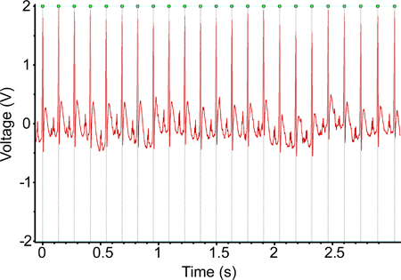
Figure 1. An ECG recording obtained using the implanted telemetry device one week post-implantation. The signal seen in this recording is largely typical of the recordings obtained using these devices.

Figure 2. An ECG recording obtained using the implanted telemetry device six months after implantation. There is negligible degradation of the signal being recorded over that time period, and this signal is certainly adequate for calculation of the animal heart rate.

Figure 3. A 3D reconstruction of a successful electrode placement, using combined X-ray computed tomography and histological sections. Both electrode shanks penetrated the posteroventral cochlear nucleus with electrodes oriented to face the structure.

Figure 4. The map of electrophysiological responses recorded with the electrode placement of Figure 3. Each histogram shows data for activity at one electrode site in response to presentation of one acoustic frequency; each column represents a 25 ms time period. On both shanks of the electrode array, responses are detected at each individual electrode site only in response to a quite narrow band of frequencies, but these narrow bands are distributed across a broad range of frequencies. Such a distribution is ideal, as many distinct frequency-associated regions of the brain can be stimulated independently.

Figure 5. The electrophysiological response at channel 10 from the implant presented in Figures 3 & 4. Ideally, electrode placements should lead to neural responses to acoustic stimulus being detected on several channels with sound amplitude as low as 10 dB, as appears in this example.

Figure 6. A 3D reconstruction of a poor electrode placement. While the caudorostral angle of the electrode was correct, it was too medial. Furthermore, the electrode was not inserted sufficiently deep, resulting the in sites nearest the tip of the electrode being located within the dorsal cochlear nucleus.

Figure 7. The map of electrophysiological responses recorded with the electrode placement as shown in Figure 6. Activity is occurring at the tips of each shank of the electrode array, but there is little variation in the acoustic stimulus frequency that elicits activity at each electrode site. Such an implantation does not enable stimulation of distinct frequency layer for discrimination testing.

Figure 8. The electrophysiological response at channel 28 on the electrode placement shown in Figures 6 & 7. Acoustic stimulus produce strong bursts of activity, similar in spike frequency to that seen in the very successful implantation (Figure 3). Threshold is also quite low, with responses being detected in response to tones at 20 dB. If there were greater variation in the frequencies to which the strongest responses occurred across other channels of the array this channel would certainly be adequate for stimulation.
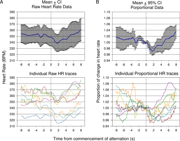
Figure 9. Comparison of raw heart rate (A) verses mean proportional (B) data collected during the first conditioning session in one animal. Responses from 7 presentations are shown. Because of the variation in starting heart rate prior to commencement of the tone alteration, mean raw heart rate (±95% confidence intervals) does not adequately show the degree of change of an initial drop in heart rate followed by rise as indicated in individual raw traces (A, bottom). Mean proportional change in heart rate data in which the heart rate is divided by the heart rate at time of conditioned acoustic stimulus presentation for each trace is presented in (B). This shows a statistically significant drop following conditioned stimulus presentation with a late significant rise reflected using 95% confidence intervals. Individual proportional heart rate traces are shown (B, bottom).
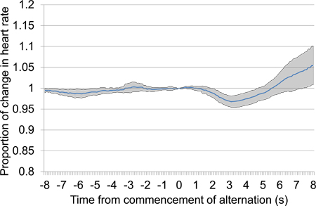
Figure 10. Mean proportional heart rate change from 8 s prior to 8 s after the commencement of alternating acoustic stimulus presentation, combining data from the second and third conditioning sessions. The presented data includes seven trials presented over the two conditioning sessions, four in the first conditioning session and three in the second. In response to alternating stimulus presentation, a large initial drop in heart rate occurred followed by a late increase in heart rate.
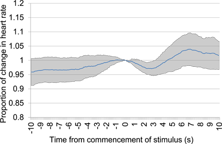
Figure 11. Mean proportional heart rate change from 10 s prior to 10 s after the commencement of acoustic stimulus presentation after a 30 s silence period. Trial data was taken from the first testing session and includes six acoustic stimulus presentations. A clear early drop in heart rate provides evidence of discrimination between the acoustic stimuli presented.

Figure 12. Mean proportional heart rate change from 8 s prior to 8 s after the commencement of alternating acoustic stimulus presentation, taken from the first testing session and including five acoustic stimulus presentations. A clear early drop in heart rate provides evidence of discrimination between the acoustic stimuli presented.
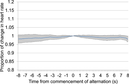
Figure 13. Mean proportional heart rate change from 10 s prior to 10 s after the commencement of electrical brain stimulation after a 30 s silence period. Trial data was taken from the first and second testing sessions and includes 18 electrical stimulation presentations, all using the same stimulation settings. The absence of any particular drop in heart rate, particularly proximal to time 0 at which stimulation commences, suggests that the animal is unable to detect the stimulus.

Figure 14. Mean proportional heart rate change from 8 s prior to 8 s after the commencement of alternating electrical stimulus presentation (refer 4.6.5 and 4.6.6), taken from the first testing session and including 33 electrical stimulus presentations. No consistent pattern of change in heart rate occurs near time 0, which suggests that the alternating stimuli are insufficiently different for discrimination to occur.
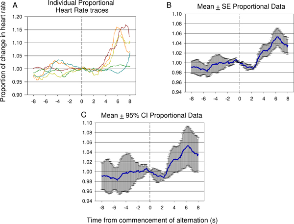
Figure 15. Representative examples of individual traces (A) and mean proportional heart rate data (B,C) from 8 s prior to 8 s after the commencement of alternating electrical stimulus presentation, taken from the seventh testing session of a second animal, and including 12 electrical stimulus presentations. A significant decrease in HR occurs rapidly after introduction of the second neural stimulus followed by a significant rise in heart rate reflected suggesting the difference between the first and second stimulus has been detected by the animal. The degree of error and variance of the response can be seen in the proportional mean ± standard error (SE) plot shown in (B). The significance of the dip and rise following the second stimulus presentation can be verified using 95% confidence intervals applied to the data shown in (C). The response seen in (C) is similar to the response see in Figure 9 B.
Discussion
The techniques described here provide a means for testing a range of discrimination tasks rapidly, with short training times and allowing for substantial automation, thus minimising researcher time required for data processing. Using data obtained from the implanted ECG, calculation of heart-rate (HR) change at times of stimulus presentation can be automated. Errors in ECG processing (such as missing a single heart-beat) can be easily identified as they produce spuriously large changes in apparent heart-rate for a very brief period, and such easy error detection minimises the requirement for time-intensive manual data review.
The technique described for the implantation of the ECG telemetry device consistently produces recordings with little or no interference (see Figures 1 & 2). However, relatively small variations in the placement of the lead in the mediastinum region can lead to interference from nearby muscles and particular respiration-associated noise. Verifying correct placement of the leads during the implantation process, particularly after suturing leads in place, allows fine adjustments of lead placement to minimise interference.
The process of brain implantation into the cochlear nucleus is difficult. By using serial presentations of band-pass filtered noise of several frequency ranges, rather than broadband noise as has previously been used3, responses of cell populations at electrode sites can be rapidly reviewed in terms of frequency-response rather than the less-specific noise response. The ability to rapidly identify when a sufficient range of frequency-tuned cell populations are accessible is critical in research when electrical stimulus discrimination is being tested. If insufficient frequency-distribution is obtained, then comparison between stimulation of distinct frequency areas is simply not possible. Nonetheless, the longer process of frequency-amplitude response mapping remains critical to providing detail regarding the broadness of tuning of cell populations and should be performed prior to fixing the electrode in place.
In behavioral training and testing, the inclusion of a non-stimulus (or silent) period between trials, prior to stimulus onset, allows the response to initial stimulus onset to be examined. When using electrical neural stimulation, a response to stimulus onset provides evidence for the simple detection of the stimulus. Thus, when there is no stimulus onset response, but a response when the second alternation stimulus is introduced, it can be deduced that only the latter stimulus can be detected. Without inclusion of such a silent period, there would be no way to determine that the former stimulus was not detected.
A limitation in this behavioral testing technique is that the absence of foot-shocks delivered after the presentation of neural stimulation may lead to the development of specificity in conditioned fear, such that fear is only expressed when acoustic stimulus is presented. That is, the animal may learn that the particular sensory effects of neural stimulation are associated with not receiving a foot shock. In contrast, delivering foot-shocks after the presentation of neural stimulation could lead to a conditioned fear of the neural stimulus itself, distinct from any sound-like properties the neural stimulus may have. Results obtained when excluding a foot-shock after neural stimulation certainly provide stronger evidence for neural stimulus being sound-like than those using a foot-shock after neural stimulation, as in the former case conditioned fear has generalised from acoustic to neural stimulation. Nonetheless, the risk of developing specificity to acoustic rather than neural stimulation is present. The use of band-pass filtered noise as acoustic stimulus rather than pure tone bursts, the former of which may better reflect the perceptual experience of neural stimulation, could reduce the risk of such specificity developing. However, such a procedure introduces the additional variable of band-width of the filter, which will affect discrimination tasks.
An additional limitation associated with any chronic neural implantation, such as required for behavioral testing, is the change in function of the electrode or the associated neural tissue over time. Stimulation of neural tissue can lead to both temporary suppression of neural activity13 and tissue changes such as cell loss14 and direct brain tissue response to the electrode.15
The described approach to implantation and behavioral testing provides a means to test both detection and discrimination of acoustic and electrical stimuli with brief training, and the ability to exert control of trial frequency. The technique of using change in HR as a measure of conditioned fear may be applicable to not only auditory testing, but more generally to any sensory testing in which stimuli can be presented for any discrete period, and in which detection of sensory discrimination is desired.
Disclosures
Dr. Antonio Paolini is a Director of Bioengenesis Technologies Pty Ltd who are the Australian representatives for Tucker Davis Technologies and the Australian distributor of NeuroNexus Probes.
Acknowledgments
Funding for this research was provided by The Garnett Passes and Rodney Williams Memorial Foundation and La Trobe University.
Materials
| Name | Company | Catalog Number | Comments |
| PowerLab |  ADInstruments ADInstruments |
ML880 | Records data received from the implanted TR40 transmitter |
| SmartCtrl controller card | Med Associates, Inc. | DIG-716B | Controls the behavioral test chamber, including foot shock |
| Modular behavioral test chamber | Med Associates, Inc. | ENV-009 | Test chamber size: 30.5cm x 39.4cm |
| Aversive stimulus generator | Med Associates, Inc. | ENV-410B | Delivers aversive foot-shock to metal-bar floor of the cage through a Solid State Scrambler unit |
| Programmable Attenuator | TDT | PA5 | Controls the amplitude of delivered acoustic signal to ensure stable amplitude across frequencies |
| Electrostatic speaker driver | TDT | ED1 | Drives the electrostatic speakers (EC1, ES1) |
| Free-field electrostatic speaker | TDT | ES1 | Sounds are presented using this speaker in the behavioral test chamber |
| Coupled electrostatic speaker | TDT | EC1 | Sounds are presented using this speaker during neural implant surgery |
| Stimulator Base Station | TDT | RX7 | Controls delivery of electrical neural stimulation (used with MS16) |
| Microstimulator | TDT | MS16 | Delivers multichannel electrical neural stimulation |
| Processing base station | TDT | RZ2 | Records neural activity during brain implantation (using PZ2 preamplifier) |
| Preamplifier | TDT | PZ2-256 | 256-channel high impedance preamplifier |
| Telemetry device receiver | Telemetry Research | TR162 | Receives digital signal from TR40, and converts to amplified analogue output |
| Implantable electrocardiogram telemetry device | Telemetry Research | TR40 | The implanted transmitter device, sampling at 2kHz |
| Multifunction Processor | Tucker-Davis Technologies | RX6 | Used to generate acoustic stimuli |
| Vertex Castavaria | Vertex Dental | Dental acrylic used to fix the electrode in place | |
| Kwik-Sil Adhesive, low viscosity | World Precision Instruments, Inc. | Silicon elastomer used to coat the electrode shanks | |
| Multichannel electrode | NeuroNexus Technologies | a2x16-10mm 100-500-413 | The 2-shank 32-channel extracellular electrode array used for implantation. The electrode sites have been activated to produce a coating of iridium oxide in preparation for stimulation. |
References
- Mauger, S. J., Shivdasani, M. N., Rathbone, G. D., Argent, R. E., Paolini, A. G. An in vivo investigation of first spike latencies in the inferior colliculus in response to multichannel penetrating auditory brainstem implant stimulation. Journal of Neural Engineering. 7, 036004-036004 (2010).
- Shivdasani, M. N., Mauger, S. J., Argent, R. E., Rathbone, G. D., Paolini, A. G. Inferior colliculus responses to dual-site intralamina stimulation in the ventral cochlear nucleus. J. Comp. Neurol. 518, 4226-4242 (2010).
- Shivdasani, M. N., Mauger, S. J., Rathbone, G. D., Paolini, A. G. Inferior colliculus responses to multichannel microstimulation of the ventral cochlear nucleus: Implications for auditory brain stem implants. Journal of Neurophysiology. 99, 1-13 (2007).
- Lenarz, M., Lim, H. H., Patrick, J. F., Anderson, D. J., Lenarz, T. Electrophysiological Validation of a Human Prototype Auditory Midbrain Implant in a Guinea Pig Model. JARO. 7, 383-398 (2006).
- Lim, H. H. Auditory Cortical Responses to Electrical Stimulation of the Inferior Colliculus: Implications for an Auditory Midbrain Implant. Journal of Neurophysiology. 96, 975-988 (2006).
- Otto, K. J., Rousche, P. J., Kipke, D. R. Microstimulation in auditory cortex provides a substrate for detailed behaviors. Hearing research. 210, 112-117 (2005).
- Gai, Y. Detection of Tones in Reproducible Noise Maskers by Rabbits and Comparison to Detection by Humans. JARO. 8, 522-538 (2007).
- Miller, C. A., Woodruff, K. E., Pfingst, B. E. Functional responses from guinea pigs with cochlear implants. I. Electrophysiological and psychophysical measures. Hearing Research. 92, 85-99 (1995).
- Beitel, R. E., Vollmer, M., Snyder, R. L., Schreiner, C. E., Leake, P. A. Behavioral and neurophysiological thresholds for electrical cochlear stimulation in the deaf cat. Audiology & Neurotology. 5, 31-38 (2000).
- Beitel, R. E., Snyder, R. L., Schreiner, C. E., Raggio, M. W., Leake, P. A. Electrical cochlear stimulation in the deaf cat: comparisons between psychophysical and central auditory neuronal thresholds. J. Neurophysiol. 83, 2145-2162 (2000).
- Vollmer, M., Beitel, R. E., Snyder, R. L. Auditory detection and discrimination in deaf cats: Psychophysical and neural thresholds for intracochlear electrical signals. Journal of Neurophysiology. 86, 2330-2343 (2001).
- LeDoux, J. E., Cicchetti, P., Xagoraris, A., Romanski, L. M. The lateral amygdaloid nucleus: sensory interface of the amygdala in fear conditioning. Journal of Neuroscience. 10, 1062-1069 (1990).
- McCreery, D. B., Yuen, T. G., Agnew, W. F., Bullara, L. A. A characterization of the effects on neuronal excitability due to prolonged microstimulation with chronically implanted microelectrodes. IEEE Transactions on Biomedical Engineering. 44, 931-939 (1997).
- Liu, X., McPhee, G., Seldon, H. L., Clark, G. M. Histological and physiological effects of the central auditory prosthesis: surface versus penetrating electrodes. Hearing Research. 114, 264-274 (1997).
- Polikov, V. S., Tresco, P. A., Reichert, W. M. Response of brain tissue to chronically implanted neural electrodes. Journal of Neuroscience Methods. 148, 1-18 (2005).
