We describe here an improved Luminescence Resonance Energy Transfer (LRET) method where we introduce a protease cleavage site between the donor and acceptor fluorophore sites. This modification allows us to obtain specific LRET signals arising from membrane proteins of interest, allowing for the study of membrane proteins without protein purification.
A subscription to JoVE is required to view this content. Sign in or start your free trial.
Method Article
Luminescence Resonance Energy Transfer to Study Conformational Changes in Membrane Proteins Expressed in Mammalian Cells
In This Article
Summary
Abstract
Luminescence Resonance Energy Transfer, or LRET, is a powerful technique used to measure distances between two sites in proteins within the distance range of 10-100 Å. By measuring the distances under various ligated conditions, conformational changes of the protein can be easily assessed. With LRET, a lanthanide, most often chelated terbium, is used as the donor fluorophore, affording advantages such as a longer donor-only emission lifetime, the flexibility to use multiple acceptor fluorophores, and the opportunity to detect sensitized acceptor emission as an easy way to measure energy transfer without the risk of also detecting donor-only signal. Here, we describe a method to use LRET on membrane proteins expressed and assayed on the surface of intact mammalian cells. We introduce a protease cleavage site between the LRET fluorophore pair. After obtaining the original LRET signal, cleavage at that site removes the specific LRET signal from the protein of interest allowing us to quantitatively subtract the background signal that remains after cleavage. This method allows for more physiologically relevant measurements to be made without the need for purification of protein.
Introduction
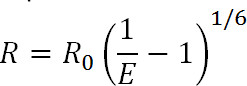
Luminescence Resonance Energy Transfer (LRET) is a derivative of the well-known Fluorescence Resonance Energy Transfer (FRET) technique1. Similar to FRET, LRET can be used to measure distances and distance changes between donor and acceptor fluorophores attached to specific sites on the protein of interest within the range of 10-100 Å1-3. The principles of LRET are also similar to FRET in that resonance energy transfer occurs between two proximal fluorophores when the emission spectrum of the donor fluorophore overlaps with the absorption spectrum of the acceptor fluorophore. The efficiency of this transfer is related to the distance between the two fluorophores by the following equation:
 Eq. 1
Eq. 1
where R is the distance between the two fluorophores, E is the efficiency of energy transfer, and R0, discussed below, is the Förster radius for the fluorophore pair, i.e. the distance at which efficiency of transfer is half-maximal. From this equation, one can see that efficiency is related to the magnitude of the distance raised to the inverse sixth power1. It is this inverse sixth power dependence that allows for FRET and LRET measurements to be exquisitely sensitive even to small distance changes when near the R0 of the FRET pair. The ability to specifically label desired sites on proteins or other macromolecules allows one to take advantage of this sensitivity to monitor conformational changes.
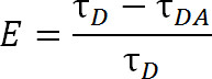
When compared to FRET, which uses conventional organic dye molecules, LRET offers additional advantages. In LRET, instead of using an organic dye as the donor fluorophore, a lanthanide series cation, typically Tb3+ or Eu3+, is used1,4-6. Fluorophores that fall under this category, e.g., terbium chelate, are also very versatile in that they can be used with a wide range of acceptor fluorophores. This flexibility is made possible because the emission spectra of chelated lanthanides contain multiple sharp emission peaks, allowing for a single species of donor fluorophore to be used with one of a wide variety of acceptor fluorophores. Thus, sensitized acceptor emission can be detected without any fear of contaminating bleed-through from donor emission5. The experimenter selects the specific acceptor based on the expected distance between the two fluorophores (Figure 1 and Table 1). In these chelated lanthanide fluorophores, the metal ion is chelated by a molecule that contains an antenna group that sensitizes the normally poorly-absorbing lanthanide to excitation as well as a bioreactive functional group to tether the ion to a specific functional group on the macromolecule1,5,6. Once excited, lanthanides relax to the ground state via the release of photons with a decay rate in the millisecond range. Because the decay is neither a singlet-to-singlet relaxation nor a triplet-to-singlet relaxation, the emission of photons cannot properly be called fluorescence or phosphorescence, but is more properly termed luminescence1. The long decay of lanthanide luminescence greatly helps in lifetime measurements. Lifetime measurements can then be used to determine efficiency via the following relation:
 Eq. 2
Eq. 2
where, E is the efficiency of transfer, τD is the lifetime of the donor (chelated lanthanide) when not participating in energy transfer, and τDA is the lifetime of the donor when participating in energy transfer with the acceptor. With LRET, τDA can also be measured as the lifetime of the sensitized acceptor emission because terbium’s lifetime is so much greater than an organic acceptor fluorophore. The acceptor emits with the same lifetime as its inciting excitation (donor lanthanide), and any contribution to the lifetime from the acceptor’s own intrinsic fluorescence lifetime is relatively negligible. By measuring the sensitized emission rather than donor emission, we also eliminate the need to ensure labeling at exactly a 1:1 ratio of donor to acceptor. Protein can instead be labeled simultaneously with both acceptor and donor fluorophores. A heterogeneously labeled population will result, but double-donor labeled proteins will not emit in the acceptor wavelength and double-acceptor labeled proteins will not be excited. Moreover, the distance between fluorophores should be the same, regardless of which cysteine site a given fluorophore attaches to, especially when using the isotropic lanthanides as a donor, so the need to specify a given site to receive either the donor or acceptor is unnecessary. Intensity may be affected with a heterogeneous population, but should still be more than sufficient to be detected.
When planning experiments, the choice of fluorophores should be dictated by the R0 value of the pair as well as the expected distance range being measured. The R0 value is defined by the following equation:
 Eq. 3
Eq. 3
where, R0 is the Förster radius in Angstroms, κ2 is the orientation factor between the two dyes (usually assumed to be 2/3), ϕD is the quantum yield of the donor, J is the spectral overlap integral between the donor's emission spectrum and the acceptor's absorbance spectrum in M-1cm-1nm4, and n is the refractive index of the medium1.
Our laboratory has added a modification to the conventional LRET technique by introducing a protease recognition site between the donor and acceptor label sites on the protein being probed. This modification allows for investigation in non-purified systems such as whole mammalian cells7. This technique is particularly useful when using cysteines as sites for labeling, since in the process of labeling with maleimide-conjugated dyes that bind to cysteine sulfhydryl groups, other proteins on the cells that have cysteines are also labeled. However, by including protease cleavage sites on the protein of interest and measuring lifetimes before and after cleavage, the experimenter can quantitatively subtract the background signal after protease cleavage from the raw signal. This subtraction isolates the specific signal arising from the protein of interest (Figure 2). Using the modification described above, LRET can be used to measure distance changes between the terbium chelate donor and the acceptor probe on a protein, and thus monitor conformational changes in the protein’s near physiological state without the requirement for purification.

Figure 1.The absorption and emission spectra of chelated terbium in black, as well as a representative acceptor, Alexa 488, in red. Notice the multiple emission peaks and the sharp, narrow emission range for each peak of terbium chelate. This pattern allows for terbium to be used with a variety of acceptor fluorophores and facilitates the measurement of sensitized emission within those ranges where terbium shows no emission. Terbium’s emission peak at 486 nm overlaps quite well with the absorption peak of Alexa 488, allowing for resonance energy transfer to occur between the two fluorophores. A wavelength of 515 nm is an excellent choice to detect sensitized emission for this pair as it is in the valley between the terbium emission peaks, and quite near Alexa 488’s emission peak of 520 nm. Note that being near the acceptor peak, though desirable, is not required—565 nm is still able to detect Alexa 488 emission without also detecting terbium emission.
| Acceptor Fluorophore | R0 (Å) | Emission wavelength (nm) |
| Atto 465 | 36 | 508 |
| Fluorescein | 45 | 515 |
| Alexa 488 | 46 | 515 |
| Alexa 680 | 52 | 700 |
| Alexa 594 | 53 | 630 |
| Alexa 555 | 65 | 565 |
| Cy3 | 65 | 575 |
Table 1. A list of commonly used acceptor fluorophores for LRET using terbium chelate as the donor11. The R0 values were measured when the donor and acceptor were attached to the soluble agonist binding domain of AMPA receptors. It is ideal to measure the R0 value again for each new system being studied.

Figure 2. An overview of the LRET method presented. (A) The AMPA receptor is a membrane protein which undergoes conformational changes upon ligand-binding. The clamshell-shaped ligand-binding domain is circled here in red. (B) The ligand-binding domain of AMPA when not bound to protein exists in an open conformation (left). When bound to ligand glutamate, the protein closes around its ligand (right). By placing fluorophores at probative sites on the LBD, the nature of this conformational change can be seen as the distance between the fluorophores changes, which will then affect fluorescence lifetime. (C) When labeling whole cells, labeling of both the protein of interest as well as background membrane proteins may occur (left). After protease cleavage, LRET signal from the protein of interest will disappear due to the release of a soluble fragment, leaving background signal intact (right). This background signal can then be subtracted from the raw signal.
Access restricted. Please log in or start a trial to view this content.
Protocol
1. Create the Construct Containing the Protein of Interest
Clone the gene expressing the protein of interest into a suitable vector. Use vectors such as the pcDNA series or pRK5 as they are well suited for expression in mammalian systems like HEK293 and CHO cells.
2. Select the Sites on the Protein to be Tagged with the Fluorophores
- Choose labeling sites that are able to reflect possible conformational changes within the protein. If possible, use a crystal structure of the protein or of a homologous protein to help make this determination. If there is no crystal structure available, use online software to predict the possible structure of the protein and hence receive insight into appropriate sites.
- Choose residues such that the side chains of the selected residues are surface exposed and accessible to the fluorophores so that the protein can be labeled.
- Choose residues that are not critical to protein function, for example sites that are not involved in ligand binding.
- In introducing cysteine mutation, give preference to sites that are similar, for example serine, that would cause minimal perturbation to the protein structure.
- After choosing the labeling sites, make the mutations to ensure that the protein only gives LRET from these intended sites. Use standard site-directed mutagenesis protocols to mutate away non-disulfide-bonded cysteines that could potentially bind to maleimide-conjugated fluorescent tags. Do not mutate away disulfide-bonded cysteines and buried, free cysteines since they should not react with fluorescent dyes in the folded form of the protein.
- Introduce cysteine residues in the desired sites by making point mutations using standard site-directed mutagenesis protocols.
- Include a protease cleavage site that can specifically cleave off one of the cysteines from the protein. If the protein sequence allows for it, introduce the site by conservatively mutating the protein to have a thrombin (recognition sequence LVPRGS) or Factor Xa (recognition sequence IDGR or IEGR) sequence near the introduced cysteine and accessible to protease cleavage; otherwise the tetra- or hexa-peptide sequence may be inserted as a whole. Choose the site such that upon cleavage one of the introduced cysteines dissociates from the rest of the protein—in certain cases, this may require two cleavage sites flanking a mutated cysteine.
3. Test the Expression and Functionality of the Protein
- Perform a western blot to confirm expression of the mutated protein.
- Perform a functional assay of the protein to ensure that the mutations have altered the protein function only minimally, if at all, to avoid studying conformational changes of a dysfunctional protein.
NOTE: Since all proteins have different functions, there is no single functional assay that is used specifically for LRET; however, some examples of functional assays include enzyme activity assays for enzymes, ligand-binding assays for receptors, and electrophysiology studies for ion channels.
4. Select the Fluorophores to be Used
Select fluorophores based on the expected distance range being measured such that the range is between 0.5-1x the R0 of the fluorophore pair.
NOTE: This allows for an easier subtraction of the background, which typically has much longer lifetimes. For example, if the expected distance range being measured is around 35 Å, an appropriate fluorophore pair to use would be terbium chelate as the donor and Alexa 594 as the acceptor, because the R0 for this pair is 53 Å (Table 1).
5. Express the Protein by Transiently Transfecting the Required Amount of Mammalian Cells
Transiently transfect the protein of interest into the chosen mammalian cells using any of the common transfection reagents. Typically, use four 10-cm dishes per LRET experiment for HEK and CHO cell lines; however, this amount may vary depending on protein expression, stability, etc. Allow the cells to express the protein for 36-48 hr before harvesting.
6. Label the Proteins
- Detach cells from the culture dish. Detach HEK cells by simply pipetting buffer against the bottom of the dish. Detach CHO cells with a cell scraper, washing off the media with extracellular buffer.
- Collect the cells by centrifugation at 1,100 x g for 3 min. Use these same centrifuge settings for collecting cells after labeling, as well as after the subsequent washes.
- Suspend cells in 3 ml of extracellular buffer, then add donor and acceptor fluorophores in equimolar amounts up to a final concentration of 100-300 nM. Incubate on a rotator for 1 hr at RT.
- Wash these labeled cells 3-4x with extracellular buffer to remove unbound fluorophores, then suspend these cells in extracellular buffer (usually 2 ml) for LRET measurements.
- As a control, label a separate set of cells with only donor fluorophore (terbium chelate) without addition of any acceptor fluorophore.
NOTE: Data from these donor-only experiments is necessary to complete analysis. These experiments can be done on the same or different days. - Again, perform functional validation, this time with labeled mutant protein, as the labeling process may also interfere with function depending on the site used for labeling.
NOTE: These experiments can be done on the same or different days.
7. Set up the LRET Experiment
- Place the resuspended cells in a quartz cuvette with a minimum volume of 1 ml.
- Turn on the computer and the instrument and adjust the parameters of the data acquisition program accordingly.
- Set the excitation wavelength to the absorbance range of the donor fluorophore (330-340 nm works well for terbium chelate).
- Set the emission wavelength appropriately, keeping in mind that the acceptor emission varies based on the acceptor used. Importantly, select a detection wavelength that measures only the acceptor emission and does not include any bleed-through from the donor’s emission. For example, use a wavelength of 565 nm for Alexa 555 as an acceptor Table 1. For donor-only measurements, in which protein was labeled only with donor but without acceptor, use a wavelength of 545 nm for measuring terbium chelate emission.
- Set the length of emission detection to be at least three times the expected LRET lifetime to ensure that a long-lifetime component will not be missed.
- Perform the scan. Do at least three scans of 99 sweeps to ensure consistency of results. Save the results as a text file (*.txt).
- To measure conformational changes of a protein with regard to different conditions (such as the addition of a ligand), alter those conditions and again perform at least three scans of 99 sweeps each on the same sample under this new condition. If studying the effects of glutamate on the conformation of glutamate receptors, for example, add glutamate to 1 mM to the same sample scanned in step 7.3, and then scan again.
- Add up to five units of the appropriate protease and take scans continually until cleavage is complete and no further change is seen in the lifetime for three successive scans. Usually, cleavage is complete in two to 3 hr. If a Factor Xa cleavage site is being used for protease cleavage, for example, add 3 µl of Factor Xa to the sample, and scan every 30 min for 3 hr.
8. Analyze the Data Obtained
- Open the data analysis software.
- Load the fluorescence lifetime data by using Import ASCII to open the text files. Load all the replicates as well as the final background measurements, into one file.
- Average the data from all the scans for each experimental condition to get the final data. To do so, highlight the columns that contain the individual trials, then under the Data menu in the menu bar, click on Statistics on Rows to display the average fluorescence intensities from the trials, as well as the standard deviation and standard error.
- Plot the average values as a line graph with fluorescence intensity on the Y-axis and lifetime in microseconds on the X-axis to create a curve that represents the lifetime of the sensitized emission of the acceptor. Change the Y-axis of the plot to a log scale, to allow for better visualization of the data.
- Repeat step 8.3 on the background measurement data, averaging the final scans that show overlap indicating complete cleavage.
- Display the mean background data on the same plot that contains the averaged raw data. To do so, open the Layer Control dialog box found under the Plot menu. Then, transfer the data containing the background mean into the list of Layer Contents.
- Align the mean background data to the mean raw data. To do so, use the Simple Math function under the Math menu to multiply or divide the background data as needed until the tail end of the background overlaps with the tail end of the raw data.
NOTE: At this tail end, the lifetime from the protein of interest should have already completely decayed away; what is aligned is simply the background signal present both before and after protease cleavage. - Subtract the aligned background signal from the initial raw LRET signal, again using the Simple Math function.
- Fit the data to an exponential decay (single or multiple exponentials, depending on the sites and the experimental design).
- Set the start boundary for fitting to begin after the end of the laser pulse. Use this same startpoint for all subsequent curve fittings.
- In the Select Fitting Function dialog box, select exponential decay so as to fit the lifetime to the following equation for a single exponential decay:
 Eq. 4
Eq. 4
where, y represents the fluorescence intensity, y0 represents the background intensity due to noise from the system, A1 is the signal intensity, t is the fluorescence lifetime, x is the time, and x0 is the time offset. - Fix x0 to 0, start the Fitting Function, and fit the data.
NOTE: If the experiment is designed to have signal only from one pair of sites, the resulting data should easily be fit by a single exponential decay8. The residual of the fit is a good method to determine the goodness of the fit and if additional decay lifetimes are required.
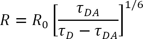
- Use the lifetimes obtained from the data to calculate the distance between fluorophores using the Förster equation (a rearrangement of Equations 1 and 2 above):
 Eq. 5
Eq. 5
NOTE: All the variables are as mentioned above with τDA having been measured as the sensitized acceptor emission lifetime. Further details and examples on measurements of R0 and R can be found elsewhere7,9,10. - Repeat the experiment and data analysis at least three times to ensure reproducibility. Inconsistency between individual repetitions of the same measurement calls into question the validity of the data; use additional control experiments or repetitions. Calculate errors in measurement using the free Gustavus Error analysis calculator (developed by Dr. Thomas Huber) or a similar system that propagates the error in the fits of the lifetime.
Access restricted. Please log in or start a trial to view this content.
Results
A successful LRET measurement with a lanthanide donor should have a donor only lifetime in the millisecond time range. The lifetime of sensitized LRET emission for the protein labeled with both the donor and the acceptor will be notably shorter, with a lifetime in the microsecond range after background subtraction Figure 3. Protease cleavage results in an increase in lifetime that should become stable over time (i.e. no longer changing), showing that the protease cleavage is complete Fig...
Access restricted. Please log in or start a trial to view this content.
Discussion
LRET is a powerful technique that allows scientists to measure distances between domains within a single protein as well as between subunits in a multimeric protein. As such, LRET is well-suited to examining the conformational changes and dynamics of proteins or other macromolecules. The above protocol should allow the properly equipped lab to easily test their hypotheses; however, there are many common sources of error that may plague the new investigator. If little or no LRET signal is seen, first check the wavelength ...
Access restricted. Please log in or start a trial to view this content.
Disclosures
The authors have nothing to disclose.
Acknowledgements
This work was supported by National Institutes of Health Grant GM094246, the American Heart Association Grant 11GRNT7890004, and the National Science Foundation Grant MCB-1110501.
Access restricted. Please log in or start a trial to view this content.
Materials
| Name | Company | Catalog Number | Comments |
|---|---|---|---|
| LanthaScreen Thiol Reactive Tb Chelate | Life Technologies | PV3579 | |
| Acceptor fluorophore-Fluorescein-5-Maleimide | Life Technologies | F-150 | Choice of acceptor depends on the specific experiment |
| Acceptor fluorophore-Alexa Fluor 488 C5 Maleimide | Life Technologies | A-10254 | Choice of acceptor depends on the specific experiment |
| Acceptor fluorophore-Alexa Fluor 555 C2 Maleimide | Life Technologies | A-20346 | Choice of acceptor depends on the specific experiment |
| Acceptor fluorophore-Alexa Fluor 594 C5 Maleimide | Life Technologies | A-10256 | Choice of acceptor depends on the specific experiment |
| Acceptor fluorophore-Alexa Fluor 680 C2 Maleimide | Life Technologies | A-20344 | Choice of acceptor depends on the specific experiment |
| QuantaMaster 3-SS | Photon Technology International | Spectrofluorometer should have pulsed excitation with the ability to measure lifetimes in the millisecond range | |
| FluoreScan 2.0 | Photon Technology International | Data Acquisition Software used in manuscript. Software provided with fluorescence instrument | |
| Origin 8.6 | OriginLab | Origin is the data analysis software used in protocol. Can use other similar data analysis software | |
| Quartz cuvette | Starna Cells, Inc | 3-Q-10 | |
| Stir bar | Bel-Art Products | F37119-0007 | Used in cuvette to keep cells in suspension. Can use any stir bar that fits the cuvette |
References
- Selvin, P. R. Principles and biophysical applications of lanthanide-based probes. Annual Review of Biophysics and Biomolecular Structure. 31, 275-302 (2002).
- Stryer, L., Haugland, R. P. Energy transfer: a spectroscopic ruler. Proceedings of the National Academy of Sciences of the United States of America. 58, 719-726 (1967).
- Stryer, L. Fluorescence energy transfer as a spectroscopic ruler. Annual Review of Biochemistry. 47, 819-846 (1978).
- Selvin, P. R., Hearst, J. E. Luminescence energy transfer using a terbium chelate: improvements on fluorescence energy transfer. Proceedings of the National Academy of Sciences of the United States of America. 91, 10024-10028 (1994).
- Chen, J., Selvin, P. R. Thiol-reactive luminescent chelates of terbium and europium. Bioconjugate Chemistry. 10, 311-315 (1999).
- Ge, P., Selvin, P. R. Thiol-reactive luminescent lanthanide chelates: part 2. Bioconjugate Chemistry. 14, 870-876 (2003).
- Gonzalez, J., Rambhadran, A., Du, M., Jayaraman, V. LRET investigations of conformational changes in the ligand binding domain of a functional AMPA receptor. Biochemistry. 47, 10027-10032 (2008).
- Ramaswamy, S. S., Maclean, D. M., Gorfe, A. A., Jayaraman, V. Proton mediated conformational changes in an Acid Sensing Ion Channel. J. Bio. Chem. 288, (2013).
- Rambhadran, A., Gonzalez, J., Jayaraman, V. Conformational changes at the agonist binding domain of the N-methyl-D-aspartic acid receptor. The Journal of Biological Chemistry. 286, 16953-16957 (2011).
- Rambhadran, A., Gonzalez, J., Jayaraman, V. Subunit arrangement in N-methyl-D-aspartate (NMDA) receptors. The Journal of Biological Chemistry. 285, 15296-15301 (2010).
- Kokko, T., Kokko, L., Soukka, T. Terbium(III) chelate as an efficient donor for multiple-wavelength fluorescent acceptors. Journal of Fluorescence. 19, 159-164 (2009).
Access restricted. Please log in or start a trial to view this content.
Reprints and Permissions
