Microfluidics is a powerful tool for the development of diagnostic tests. However, expensive equipment and materials, as well as laborious fabrication and handling techniques, are often required. Here, we detail the fabrication protocol of an acrylic microfluidic device for magnetic micro- and nanoparticle-based immunoassays in a low-cost and simple-to-use setting.
A subscription to JoVE is required to view this content. Sign in or start your free trial.
Method Article
Computer Numerical Control Micromilling of a Microfluidic Acrylic Device with a Staggered Restriction for Magnetic Nanoparticle-Based Immunoassays
In This Article
Summary
Abstract
Microfluidic systems have greatly improved immunoassay techniques. However, many microfabrication techniques require specialized, expensive, or complicated equipment, making fabrication costly and incompatible with mass production, which is one of the most important preconditions for point-of-care tests (POCT) to be adopted in low-resource settings. This work describes the fabrication process of an acrylic (polymethylmethacrylate, PMMA) device for nanoparticle-conjugated enzymatic immunoassay testing using the computer numerical control (CNC) micromilling technique. The functioning of the microfluidic device is shown by performing an immunoassay to detect a commercial antibody using lysozyme as a model antigen conjugated to 100 nm magnetic nanoparticles. This device integrates a physical staggered restriction of only 5 µm in height, used to capture magnetic microparticles that make up a magnetic trap by placing an external magnet. In this way, the magnetic force on the immunosupport of conjugated nanoparticles is enough to capture them and resist flow drag. This microfluidic device is particularly suitable for low-cost mass production without the loss of precision for immunoassay performance.
Introduction
In recent years, microfluidics has played an important role in immunoassay techniques1. Miniaturization technology has many outstanding advantages compared to traditional immunoassays, such as reduced sample and reagent consumption, shorter incubation times, efficient solution exchange, and higher integration and automation2.
Furthermore, microfluidic systems in immunoassays, in association with magnetic nanoparticles as immunosupport, considerably reduce incubation times, achieving high detection sensitivity due to the increased surface-to-volume ratio3. Brownian movement of the particles improves the reaction kinetics during the formation of the antigen-antibody complex4,5. Moreover, the magnetic properties of nanoparticles provide the versatility to be integrated into different microfluidic device configurations, making them an ideal candidate for signaling and molecule capture in miniaturized on-chip biosensing systems5. However, magnetic forces are significantly weaker than drag forces at the nanometer scale due to the high surface-to-volume ratio6. Therefore, capturing nanoparticles for crucial immunoassay steps such as washing and detection can be challenging, and a conventional magnet is insufficient4.
An efficient way to manipulate the nanoparticles is the use of a microfluidic magnetic trap formed by iron microparticles, which are packed in a microfluidic structure3. Therefore, when an external magnet approaches, a complex interaction is created within the magnetized porous medium between the magnetic and flux forces. The magnetic force acting on the nanoparticles is strong enough to capture them and resist flow drag3,4,7. This approach requires microfabrication techniques that achieve resolutions in the order of a few micrometers to generate micrometric structures that retain the microparticles.
Current microfabrication techniques allow the high-resolution fabrication of structures from a few microns to hundreds of nanometers8. However, many of these techniques require specialized, expensive, or complicated equipment. One of the main difficulties is the requirement for a cleanroom for mold fabrication, which remains costly and time-consuming8,9. Recently, microfluidic engineers have overcome this drawback by developing a variety of alternative fabrication methods, with various advantages such as reduced costs, faster turnaround times, cheaper materials and tools, and increased functionality8. In this way, the development of new microfabrication techniques brought low-cost, non-cleanroom methods that achieve resolutions as low as 10 µm8. Patterning can be used directly on a substrate without generating an expensive molding pattern, thus avoiding a time-consuming process. Direct fabrication methods include CNC milling, laser ablation, and direct lithography8. All these methods are suitable for producing high-aspect-ratio channels in a wide range of materials, regardless of their hardness9, enabling new and advantageous geometries, physical behaviors, and qualities in microfluidic devices8.
CNC micromilling creates microscale structures using cutting tools that remove bulk material from a substrate and is an effective fabrication method for microfluidic devices10,11. The micromilling technique can be useful in microfluidic applications to create microchannels and features directly on the work surface, offering a key advantage: a workpiece can be fabricated in a short time (less than 30 min), significantly reducing the turnaround time from design to prototype12. In addition, the wide availability of cutting accessories of different materials, sizes, and shapes makes CNC milling machines a suitable tool that has allowed the fabrication of different features in many types of low-cost disposable materials13.
Among all the materials commonly used in micromilling, thermoplastics remain a leading choice due to their many favorable properties and compatibility with biological applications10,14. Thermoplastics are an attractive substrate for microfluidic systems due to their significant advantages for developing low-cost, disposable analytical systems9. In addition, these materials are highly amenable to high-volume manufacturing processes, making them suitable for commercialization and mass production. For these reasons, thermoplastics such as PMMA have been considered reliable and robust materials since the early years of microfluidics10. Different protocols have been described to fabricate closed channels in thermoplastics, such as solvent bonding15, heat bonding16, and ultraviolet (UV)/ozone surface treatment bonding17.
In many cases, the positioning resolution achieved with conventional micromilling machines is not sufficient for some microfluidic applications that require structures smaller than 10 µm. High-end micromilling has enough resolution. Unfortunately, due to high prices, its use is limited to a handful of users12. Previously, our research group reported the fabrication and manipulation of a low-cost tool that allows machining structures of less than 10 µm, overcoming the resolution of conventional milling machines12. The fixture is a platform manufactured by 3D printing with simple electronics, containing three piezoelectric actuators. The surface contains hinge-shaped joints that allow it to be lifted when the piezoelectric elements act simultaneously. Z-axis displacement can be controlled with a resolution of 500 nm and an accuracy of ±1.5 µm12.
This paper presents the steps of the manufacturing process of an acrylic device (PMMA) through a micromilling technique. The chip design consists of a main channel 200 µm wide and 200 µm high and a side channel with the same dimensions to purge the flow of the reagents. In the central region, the channel is interrupted by a physical restriction of only 5 µm in height, fabricated with the 3D-printed piezoelectric platform made by this group12, to capture magnetic microparticles that make up a magnetic trap for nanoparticles by placing an external magnet. We show the operation of the microfluidic device by performing an immunoassay to detect a commercial antibody using lysozyme as a model antigen conjugated to 100 nm magnetic nanoparticles. This device combines different features that make it unique4: the use of magnetic nanoparticles as immune support reduces the total test time from hours to minutes; using a fluorogenic enzyme for detection allows for limits of detection that are comparable to those of standard enzyme-linked immunosorbent assays (ELISAs); and the use of a thermoplastic as a fabrication material makes it compatible with mass production, which was not the case for previous microfluidic nanoparticles' magnetic traps3, and makes it an excellent candidate to develop POCT.
Access restricted. Please log in or start a trial to view this content.
Protocol
1. Micromilling
- Surface grinding
- Turn on the micromilling machine and the piezoelectric controller. Start their respective control software12.
- Select the required end mill bits (200 µm and 800 µm diameters). Place them in the appropriate compartment of the milling machine (Figure 1).
- Cut 9 mm x 25 mm rectangles of 1.3 mm thick PMMA with the 800 µm end mill bit. Attach one of these rectangles carefully with double-sided adhesive tape to the piezoelectric platform (Figure 2).
NOTE: Make sure to always place the acrylic rectangle in the same position so that one of the corners coincides with the origin coordinates on the x- and y-axes for machining. - Connect and place the z-sensor on the surface of the PMMA rectangle. Select the detection pin and move it over the sensor surface. Lower the pin manually without contacting the sensor. Activate the Z0 sensing mode (Figure 3).
- Select the 200 µm end mill bit and move it to the x, y origin. Remove the z-sensor. Lower the bit carefully without contacting the acrylic surface.
- Spin the 200 µm end mill bit at 14,500 rpm. Slowly lower it to the origin coordinate on the z-axis (z = 0). Reset the z-axis 30 µm below the origin. Set this coordinate as the new z-origin.
NOTE: Never lower the bit if it is not rotating. Otherwise, it risks breaking. - Click on the Cut button in the micromilling machine software to activate the Cut panel. Click on the Add button and select the .txt file (Supplemental Coding File 1) with a previously created code for the grinding of the acrylic surface. Click on the Output button to start the process.
- Bring the end mill bit to the coordinate where the restriction will be machined. Prevent the end mill bit from lifting off the ground surface once this coordinate is reached by clicking the Pause button. Otherwise, manually reposition the end mill bit to this coordinate (Figure 4A).
- Milling of the 5 µm restriction
- Set the speed of rotation of the end mill bit to 11,000 rpm. Raise the platform 6.5 µm with the interface of the piezoelectric platform (Supplemental Figure S1). Move the end mill bit along the y-axis by 500 µm. Return the piezoelectric platform to its initial value on the z-axis with the control interface.
- Milling of microchannels
- Open the previously created design file from the design software (Supplemental Design File 1). Click on the Print button. Access the Properties menu and click on the color window corresponding to the layer containing the design to be machined. Set the fabrication parameters in the Tool panel as specified in Supplemental Figure S2.
- Inactivate unwanted layers by selecting the None option in the Tools pull-down menu.
- Milling of holes
- Switch to the 800 µm end mill bit. Activate the design layer of the 1.2 mm diameter holes by clicking on the corresponding color window.
- Repeat step 1.3.2., but in this case, set the corresponding fabrication parameters as described in Supplemental Figure S3A for the holes.
NOTE: The depth of the machined holes is half of the acrylic thickness. - Machine two additional holes on contralateral corners of the rectangle to the alignment of the acrylic in an inverted manner on a new platform (Figure 4B). Peel off the acrylic rectangle from the piezoelectric platform. Flip the acrylic and tape it with double-sided adhesive tape over the adapter with the machined pillars (Figure 4C,D).
- Open the file with the design of the holes for the opposite face from the design software (Supplemental Design File 2). Set the corresponding fabrication parameters as described in Supplemental Figure S3B. Mill the remaining half of the reagent inlet and outlet holes with a diameter of 1.5 mm and a depth of 0.7 mm (Supplemental Figure S3C).
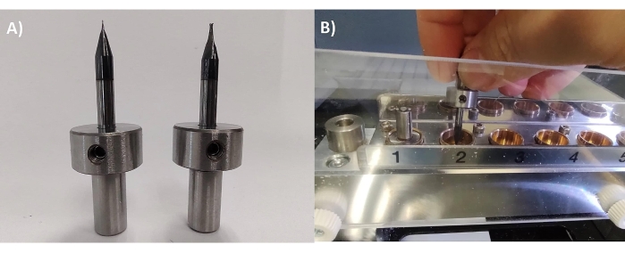
Figure 1: End mill bit placement. (A) The 200 µm and 800 µm end mill bits are placed and fixed through a screw to the steel support. (B) Each end mill bit is placed in the specific compartment of the micromilling machine for automatic selection. Please click here to view a larger version of this figure.
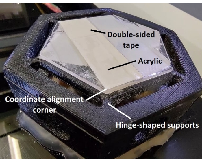
Figure 2: Piezoelectric platform. The platform is fabricated by 3D printing and consists of two hexagonal bases joined by hinges that allow a fine displacement in the z-axis controlled by three piezoelectric actuators. An acrylic adapter is also observed, on which the PMMA rectangle is attached, and which allows for setting of the alignment corner of the coordinates. Please click here to view a larger version of this figure.
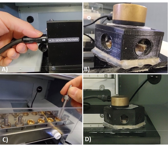
Figure 3: Z-axis calibration. The steps of the z-axis calibration are detailed. (A) The z-sensor includes a cable that plugs into the micromilling machine. (B) The sensor is placed directly onto the surface to be machined. (C) The detection pin consists of a metal bar placed in a special compartment next to end mill bits. (D) When both accessories come into contact, the micromilling machine automatically calculates the origin coordinate on the z-axis. Please click here to view a larger version of this figure.
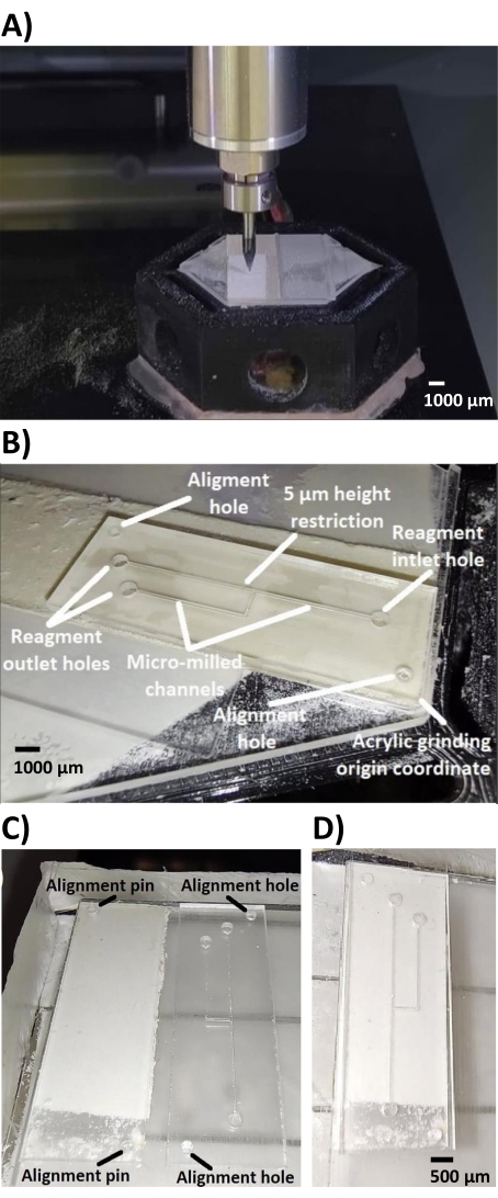
Figure 4: Rectified acrylic surface. (A) The 200 µm diameter end mill bit sweeps the entire surface of the acrylic rectangle, removing a layer approximately 30 µm high. (B) The image shows the different structures milled on the face of the previously rectified acrylic. Channels and holes for reagent inlet and outlet are observed. The 5 µm restriction cannot be seen with the naked eye. (C) Micromilled surface with alignment holes and adapter with alignment pillars at opposite corners. (D) The acrylic is aligned upside down on the adapter with pillars, into which the alignment holes fit. Scale bar = 500 µm. Please click here to view a larger version of this figure.
2. Channel sealing
- Acrylic cleaning
- Remove the acrylic rectangle from the pillar adapter platform. Take another unmachined acrylic rectangle. Wash both acrylic sheets with isopropyl alcohol (IPA) and rinse with distilled water. Wear gloves and avoid contact with IPA.
- Immerse the acrylic in an ultrasonic bath for 10 min (Figure 5A,B).
- Gaseous chloroform exposure
- Dry both acrylic sheets perfectly. Tape them to the inside of a glass Petri dish lid with double-sided tape. Be sure to place the side of the machined channel exposed (Figure 5C). Wear gloves and avoid touching the acrylic surface directly.
- Place the base of the glass Petri dish inside a bigger glass Petri dish (Figure 5D). Pour 1 mL of chloroform into the base of the Petri dish. Quickly place the lid with the acrylic sheets attached to the inner side.
- Immediately add distilled water to the base of the bigger Petri dish up to the level of the Petri dish lid. Allow exposure of the acrylic to chloroform gas for 1 min (Figure 5E).
NOTE: Consider that a longer exposure time to chloroform will attack the acrylic surface, and the 5 µm restriction will melt, modifying its height, or disappear completely. - Tilt the Petri dish to break the water seal created. Immediately remove the acrylic from the chloroform by uncovering the Petri dish. Be careful not to spill the water.
CAUTION: Do this process in the fume hood and use gloves since chloroform is highly toxic.
- Bonding by pressing and heating
- Peel both acrylic plates from the double-sided tape.
- Align both acrylics with the sides that were exposed to gaseous chloroform face to face, forming a sandwich. Place the acrylics in the press at 18 kgf/cm2 and a temperature of 90 °C (Figure 5F,G).
NOTE: It is recommended to place the acrylic longitudinally aligned and change its alignment after 2 min for a better seal. If, after this time, the seal is insufficient, place it back in the press for intervals of no more than 1 min. Using the stereoscope, check the status of the channels and restriction. Consider that, in case of exceeding the pressing time, there is a risk of eliminating the restriction.
- Hose attachment
- Cut 2-3 cm lengths of hose. Make a completely straight cut. Attach each hose to the holes of the device with instant-drying liquid adhesive (Figure 6A). Prevent the adhesive from getting inside the chip.
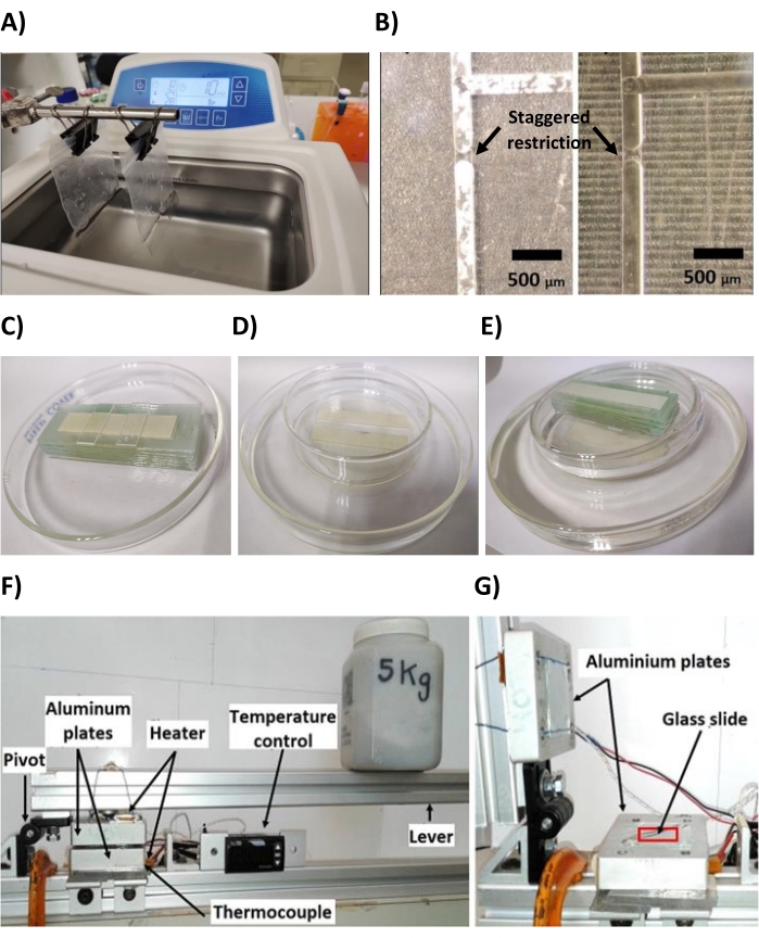
Figure 5: Sealing process of the device. (A) Each of the acrylic sheets is placed in a resealable bag with distilled water and immersed in the ultrasonic bath. (B) The image on the left shows the channels just after fabrication, and the image on the right shows the same device after washing with IPA and the ultrasonic bath, which removes all impurities and acrylic residues from the microchannel. The edges of the restriction that interrupts the central channel of 200 µm are observed, which confirms the successful milling process. Scale bars = 500 µm. (C) Both acrylics are dried and adhered to the glass platform on the lid. (D) The base of the Petri dish is placed inside another dish of larger diameter. (E) When closing the Petri dish, the water seal prevents gaseous chloroform from escaping. (F) Description of the elements of the lever with a weight of 5 kg. (G) Image of the open lever, showing in red the area where the acrylic is placed. Please click here to view a larger version of this figure.
3. Device preparation
- Fill the channels with distilled water using a syringe. Make sure there are no leaks or resistance to flow. Immerse the device in an ultrasonic bath for 10 min to remove any remaining acrylic, adhesive, or unwanted material inside the channels.
- Empty the water inside the device channels. Use a syringe to introduce a blocking solution prepared with 5% (w/v) bovine serum albumin (BSA) diluted in 1x Tris-buffered saline (TBS) and previously filtered through a 0.2 µm polyethersulfone (PES) syringe filter.
- Prepare a suspension of iron microparticles of 7.5 µm diameter in 5% BSA.
NOTE: The microparticles are previously functionalized with a silica-polyethylene glycol (PEG) layer that confers resistance to protein absorption4. - Incubate the chip and the microparticle suspension with the blocking solution for at least 1 h at room temperature. If possible, allow blocking overnight at 4 °C.
4. Microparticle trap formation
- Insert the microparticles into the chip with a syringe needle through the side channel outlet hose. Place the chip vertically and allow the microparticles to flow under the effect of gravity through the side channel. Rotate the chip 180° in two steps of 90° and allow the microparticles to target and compact at the 5 µm restriction.
- Remove excess microparticles by gravity rotating 45° toward the side channel.
- Keep the device upright to avoid undoing the microparticle trap. See Figure 6B for a summary of the microparticle trap formation process.
5. Immunoassay
- Nanoparticle preparation
- Take 2 µL of the suspension of 100 nm nanoparticles previously conjugated with lysozyme (antigen model). Add it to a 1.5 mL microcentrifuge tube with 100 µL of blocking solution. Incubate overnight at 4 °C.
- Add 150 µL of wash buffer (1x TBS, 0.05% Tween 20).
- Place the 1.5 mL microcentrifuge tube in a magnetic separator. Keep for 15 min to allow the separation of the nanoparticles (Supplemental Figure S4).
NOTE: The minimum volume for the magnetic separator is 200 µL. Avoid using a smaller volume. - Remove the liquid from the tube with a micropipette. Avoid contact with the wall of the tube where the nanoparticle pellet was formed.
- Add 250 µL of fresh wash buffer. Keep the tube under agitation for 15 min.
- Repeat steps 5.1.3.-5.1.5. 2x more, shaking only for 5 min.
- Add the desired concentration of primary anti-lysozyme antibody (see the Table of Materials). Adjust to a final volume of 100 µL in antibody diluent (1x TBS, 1% BSA, 0.05% Tween 20).
- Incubate for 15 min at 37 °C. Keep shaking for an additional 15 min at room temperature.
- Repeat the washing steps 5.1.2.-5.1.6.
- Add 100 µL of antibody diluent. Add the horseradish peroxidase-coupled secondary antibody (HRP-AbII) (see the Table of Materials) at a dilution of 1:500.
- Repeat the washing steps 5.1.2.-5.1.6.
- Keep the nanoparticles in a final volume of 50 µL of antibody diluent.
6. Experimental mounting
- Fill the two 100 µL glass syringes with water, connect a 6.5 cm long hose to each syringe, insert a metal pin into the end of the hose, and place both syringes on the computer-controlled syringe pump.
- Seal all hoses of the acrylic device with heat.
- Cut the inlet hose and keep only a few millimeters. Fill the dispensing needle with wash buffer and insert it into the cut hose. Allow the solution to drip before connecting the needle to the device to prevent air access to the device.
- Cut the outlet hose from the lateral channel. Connect to the syringe pump. Next, do the same procedure for the main channel outlet hose.
NOTE: It is key to perform steps 6.3.-6.4. in this order to avoid unpacking the microparticle trap. If possible, verify the state of the trap during these steps with the help of a magnifying glass. - Place a glass slide on the microscope stage. Attach the magnet to the slide with double-sided tape and place a small piece of tape on each side to fix the chip edges to the glass.
- Set a flow rate of 50 µL/h through the Flow Rate and Units tabs in the syringe pump controller. Select the Withdrawing mode and click on the Start button to activate the flow of the wash buffer.
- Carefully, approach the device toward the slide with the magnet in a horizontal manner so that the area of the chip containing the trap contacts the magnet.
- Stick the edges of the device to the glass with double-sided tape to prevent movement. Avoid obstructing the optical path for microscopy (Figure 6C).
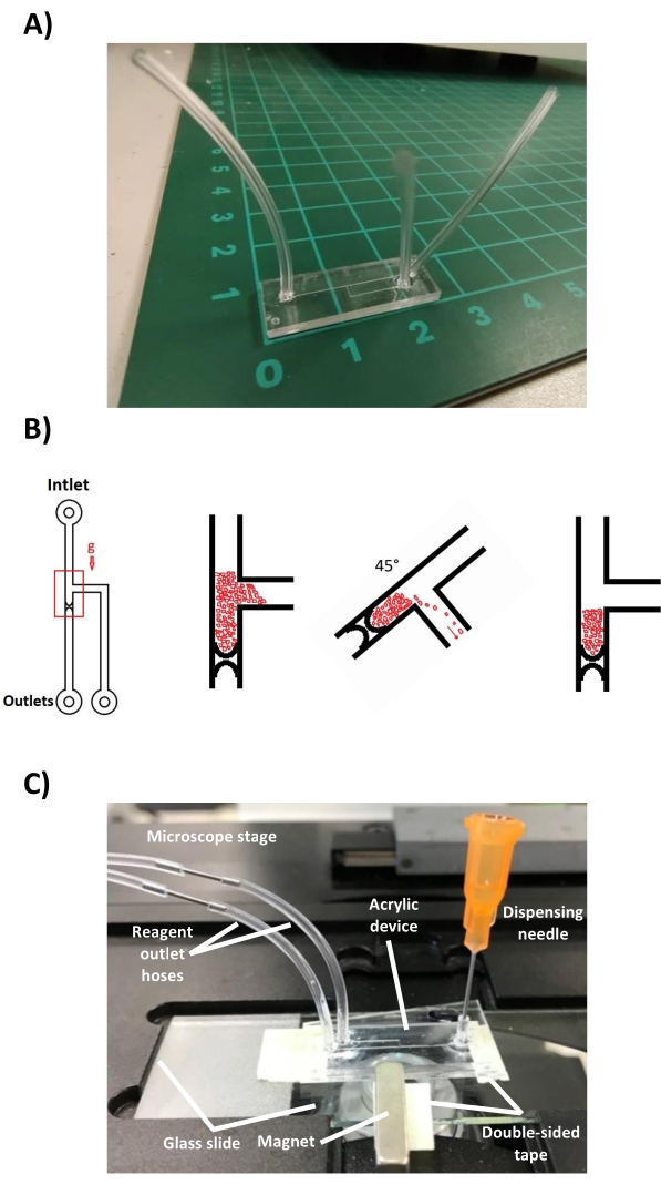
Figure 6: Final device configuration. (A) Acrylic device with the hoses attached to the corresponding inputs and outputs. The scale shows the dimensions of the device in centimeters. (B) Protocol for the formation of the microparticle trap. Microparticles flow through the channel by gravity when the device is placed in a vertical position. Microparticles are concentrated at the 5 µm restriction. Excess microparticles are easily removed by rotating the chip through the side channel. The chip is kept vertical to preserve the trap before immunoassay. (C) Microfluidic device mounted on a glass slide containing the magnet, on the stage of the inverted fluorescence microscope. The dispensing needle through which the reagents are added is observed, as well as the outlet hoses that connect to a syringe pump. Please click here to view a larger version of this figure.
7. Immunodetection
- Keep the wash buffer flowing for 10 min at 50 µL/h to remove excess BSA.
- Remove the remaining wash buffer from the dispensing needle with a micropipette. Add 50 µL of the nanoparticle suspension.
- Flow the suspension of nanoparticles for 7 min at a flow rate of 100 µL/h. Subsequently, change the flow rate to 50 µL/h and flow for another 15 min.
- Change the dispensing needle. Flow the wash buffer for 10 min at 50 µL/h. Prepare the fluorogenic substrate according to the manufacturer's specifications during the washing step.
- Remove the remaining wash buffer from the dispensing needle with a micropipette. Add 100 µL of the fluorogenic substrate (see the Table of Materials). Flow the fluorogenic substrate for 6 min at 50 µL/h.
- Set the flow rate (1 µL/h, 3 µL/h, 5 µL/h, and 10 µL/h) and time (6 min) measurement parameters in the corresponding Flow Rate and Set Timer tabs of the interface that control the syringe pump. Be sure to select Withdrawing mode for each of the measurements to be performed.
- Set an additional Flow Rate tab at 50 µL/h and Set Timer at 3 min for the wash step.
- Turn on the fluorescence of the microscope 15 s before the substrate at 50 µL/h stops. Start the image capture with the software of the microscope camera 10 s before the substrate stops with an exposure time of 1,000 milliseconds. Perform imaging for 6 min at 1 frame/s (FPS).
- Click on the Start button of the desired flow rate parameter immediately after the substrate wash flow rate at 50 µL/h stops. Click on the Start button of the wash flow (50 µL/h) immediately after the selected measurement flow stops.
- Stop the image capture and turn off the fluorescence of the microscope to avoid photobleaching of the substrate.
- Repeat steps 7.8.-7.10. for each measurement flow rate used.
Access restricted. Please log in or start a trial to view this content.
Results
It was possible to establish a highly reproducible fabrication protocol that improves the resolution of the conventional micromilling technique. Using this protocol, the fabrication of a channel as small as 5 µm in height that operates as a staggered restriction in a 200 µm high channel is achieved. The simple design of the staggered restriction captures iron microparticles of 7.5 µm diameter which, when compacted in the microchannel, allow the creation of a magnetic trap when an external magnet approaches the device. Th...
Access restricted. Please log in or start a trial to view this content.
Discussion
An acrylic microfluidic device for immunoassays using nanoparticles as immunosupport was fabricated using a micromilling technique. The method of direct manufacturing on the substrate has the advantage of avoiding the use of a master mold and the time and costs that this implies. However, it is limited to rapid prototyping and high-volume device manufacturing.
Here, we used a previously reported accessory piezoelectric platform for the milling machine12. The platform wa...
Access restricted. Please log in or start a trial to view this content.
Disclosures
The authors have no conflicts of interest to disclose.
Acknowledgements
This work was supported by Conacyt, Mexico under grant 312231 of the "Programa de Apoyos para Actividades Científicas, Tecnológicas y de Innovación", and by AMEXCID and Mexican Foreign Relations Ministry (SRE) under grant "Prueba serológica rápida, barata y de alta sensibilidad para SARS-CoV-2". JAHO thanks Conacyt Mexico for their PhD scholarship.
Access restricted. Please log in or start a trial to view this content.
Materials
| Name | Company | Catalog Number | Comments |
|---|---|---|---|
| 0.008 Endmill | KYOCERA SGS | 2204 | 2FL 0.008x1/8x0.12x1-1/12 |
| 0.032 Endmill | KYOCERA SGS | 2228 | 2FL 0.032x1/8x0.48x1-1/12 |
| Carbonyl-iron microparticles | Sigma-Aldrich | 44890 | 7 μm |
| Chloroform | Fermont | 6201 | Health Hazard: Moderate Flammability: None Reactivity: None Contact Hazard: Moderate |
| CMOS camera Moment | Teledyne Photometrics | Sensor Technology: CMOS Quantum Efficiency: 73% Pixel Size: 4.5 µm x 4.5 µm Supported Interfaces: USB 3.2 Gen 2 | |
| Dr Engrave Software | Roland DGA Corporation | Engraving software to design and create the engraving path on the surface | |
| Extraction hood | Unknown | Unknown | |
| Flexible Plastic Tubing | Tygon | AAD04103 | ID = 0.020, OD = 0.060 |
| Fluorescence microsope | ZEISS | Axio Vert.A1 | |
| High Precision Dispense Needle | Loctite | 98612 | |
| Homemade piezoelectric controller application | LabView | See reference 12 for more details. | |
| Loctite 495 instant adhesive | Henkel | 49503 | Apply with micropipette tip or dispensing needle |
| MagJET Separation Rack | thermoscientific | 12 x 1.5 mL | |
| Mechanic press | Home-made | ||
| Milling Machine | Roland | MDX-50 | |
| Piezoelectric platform | Home-made | See reference 12 | |
| Polymethylmethacrylate - Sheet - PMMA, Acrylic | Goodfellow | ME303018/1 | Thickness: 1.3 mm, Transparency: Clear/Transparent |
| PVCamTest software | Teledyne Photometrics | Version 3.10.107 | Image acquisition software |
| Stereo microscope | Nikon | SMZ 7457 | |
| SuperMag Carboxyl Beads | Ocean NanoTech | KSC0100 | 100 nm |
| Syringe pump | kd Scientific | KDS200 | Can hold up to two syringes |
| Utrasonic bath | Branson | 2800 | |
| VPanel software | Windows OS | Version 1.0.3.0 | Software for controlling the micromilling machine |
References
- Ng, A. H. C., Uddayasankar, U., Wheeler, A. R. Immunoassays in microfluidic systems. Analytical and Bioanalytical Chemistry. 397 (3), 991-1007 (2010).
- Berlanda, S. F., Breitfeld, M., Dietsche, C. L., Dittrich, P. S. Recent advances in microfluidic technology for bioanalysis and diagnostics. Analytical Chemistry. 93 (1), 311-331 (2021).
- Teste, B., et al. Microchip integrating magnetic nanoparticles for allergy diagnosis. Lab on a Chip. 11 (24), 4207-4213 (2011).
- Guevara-Pantoja, P. E., Sánchez-Domínguez, M., Caballero-Robledo, G. A. Micro-nanoparticles magnetic trap: Toward high sensitivity and rapid microfluidic continuous flow enzyme immunoassay. Biomicrofluidics. 14 (1), 014111(2020).
- Khizar, S., et al. Magnetic nanoparticles in microfluidic and sensing: From transport to detection. Electrophoresis. 41 (13-14), 1206-1224 (2020).
- Podaru, G., Chikan, V. CHAPTER 1: Magnetism in nanomaterials: Heat and force from colloidal magnetic particles. Magnetic Nanomaterials: Applications in Catalysis and Life Sciences. , Royal Society of Chemistry. Cambridge, UK. 1-24 (2017).
- Reynoso-Hernández, K. B., Guevara-Pantoja, P. E., Caballero-Robledo, G. A. Capture efficiency of magnetic nanoparticles through the compaction effect of a microparticles column. Physical Review E. 104 (2), 024603(2021).
- Gale, B. K., et al. A review of current methods in microfluidic device fabrication and future commercialization prospects. Inventions. 3 (3), 60(2018).
- Liu, K., Fan, Z. H. Thermoplastic microfluidic devices and their applications in protein and DNA analysis. Analyst. 136 (7), 1288-1297 (2011).
- Guckenberger, D. J., de Groot, T. E., Wan, A. M. D., Beebe, D. J., Young, E. W. K. Micromilling: A method for ultra-rapid prototyping of plastic microfluidic devices. Lab on a Chip. 15 (11), 2364-2378 (2015).
- Guevara-Pantoja, P. E., Jiménez-Valdés, R. J., García-Cordero, J. L., Caballero-Robledo, G. A. Pressure-actuated monolithic acrylic microfluidic valves and pumps. Lab on a Chip. 18 (4), 662-669 (2018).
- Guevara-Pantoja, P. E., Chavez-Pineda, O. G., Solis-Serrano, A. M., Garcia-Cordero, J. L., Caballero-Robledo, G. A. An affordable 3D-printed positioner fixture improves the resolution of conventional milling for easy prototyping of acrylic microfluidic devices. Lab on a Chip. 20 (17), 3179-3186 (2020).
- Friedrich, C. R., Vasile, M. J. Development of the micromilling process for high-aspect-ratio microstructures. Journal of Microelectromechanical Systems. 5 (1), 33-38 (1996).
- Malayath, G., Sidpara, A. M., Deb, S. Study of different materials response in micro milling using four edged micro end mill tools. Journal of Manufacturing Processes. 56, 169-179 (2020).
- Jiang, J., et al. A single low-cost microfabrication approach for polymethylmethacrylate, polystyrene, polycarbonate and polysulfone based microdevices. RSC Advances. 5 (45), 36036-36043 (2015).
- Sun, Y., Kwok, Y. C., Nguyen, N. T. Low-pressure, high-temperature thermal bonding of polymeric microfluidic devices and their applications for electrophoretic separation. Journal of Micromechanics and Microengineering. 16 (8), 1681-1688 (2006).
- Tsao, C. W., Hromada, L., Liu, J., Kumar, P., DeVoe, D. L. Low temperature bonding of PMMA and COC microfluidic substrates using UV/ozone surface treatment. Lab on a Chip. 7 (4), 499-505 (2007).
- Bamshad, A., Nikfarjam, A., Khaleghi, H. A new simple and fast thermally-solvent assisted method to bond PMMA-PMMA in micro-fluidics devices. Journal of Micromechanics and Microengineering. 26 (6), 065017(2016).
- Ogilvie, I. R. G., et al. Reduction of surface roughness for optical quality microfluidic devices in PMMA and COC. Journal of Micromechanics and Microengineering. 20 (6), 065016(2010).
Access restricted. Please log in or start a trial to view this content.
Reprints and Permissions
