

Summary
A “removable ceramic coating method” is presented in visual format for the synthesis of non-sintered and metal-terminated monometallic and bimetallic early transition metal carbide and nitride nanoparticles with tunable sizes and crystal structures.
Abstract
A reverse microemulsion is used to encapsulate monometallic or bimetallic early transition metal oxide nanoparticles in microporous silica shells. The silica-encapsulated metal oxide nanoparticles are then carburized in a methane/hydrogen atmosphere at temperatures over 800 °C to form silica-encapsulated early transition metal carbide nanoparticles. During the carburization process, the silica shells prevent the sintering of adjacent carbide nanoparticles while also preventing the deposition of excess surface carbon. Alternatively, the silica-encapsulated metal oxide nanoparticles can be nitridized in an ammonia atmosphere at temperatures over 800 °C to form silica-encapsulated early transition metal nitride nanoparticles. By adjusting the reverse microemulsion parameters, the thickness of the silica shells, and the carburization/nitridation conditions, the transition metal carbide or nitride nanoparticles can be tuned to various sizes, compositions, and crystal phases. After carburization or nitridation, the silica shells are then removed using either a room-temperature aqueous ammonium bifluoride solution or a 0.1 to 0.5 M NaOH solution at 40-60 °C. While the silica shells are dissolving, a high surface area support, such as carbon black, can be added to these solutions to obtain supported early transition metal carbide or nitride nanoparticles. If no high surface area support is added, then the nanoparticles can be stored as a nanodispersion or centrifuged to obtain a nanopowder.
Introduction
Early transition metal carbides (TMCs) are low-cost, earth-abundant materials that exhibit high thermal and electrochemical stability as well as unique catalytic activities.1-3 In particular, tungsten carbide (WC) and molybdenum carbide (Mo2C) have been studied extensively for their catalytic similarities to the platinum group metals (PGMs).4,5 Due to these favorable properties, TMCs have been identified as candidates for replacing expensive PGM catalysts in emerging renewable energy technologies, such as biomass conversion, fuel cells, and electrolyzers.6,7
To maximize catalytic activity, commercial catalysts are almost always formulated as ultrasmall nanoparticles (diameters <10 nm) dispersed on a high surface area support, such as carbon black.8 However, the synthesis of TMCs requires temperatures higher than ~700 °C. This leads to extensive sintering of the nanoparticles (NPs), excess surface carbon deposition (coke), and thermal support degradation. Both particle sintering and support degradation lead to decreased material surface areas. Excess surface impurity deposition blocks active metal sites, which has been shown to greatly reduce or in some instances completely eliminate the catalytic activity of TMCs.9,10 As such, the fundamental study of TMC reactivity is predominantly performed on bulk microparticles or thin films with finely controlled surfaces rather than on high surface area TMC nanomaterials.
Many methods have been developed to synthesize TMC NPs, but these methods are not suitable for synthesizing catalytically active TMC NPs. Traditional wet impregnation techniques use metal salt solutions impregnated on a high surface area support. On heating, wet impregnation methods can expose the catalyst support to destructive carburizing conditions leading to support degradation. Furthermore, sintering can only be mitigated at low wt% loadings of the metal on the support, and it is also not possible to synthesize unsupported TMC nanopowders using wet impregnation. Several newer methods involve mixing a metal precursor with a carbon precursor and applying conventional and unconventional heating techniques.11-18 Excess carbon is used to prevent sintering, but this excess carbon results in extensive surface carbon, making these materials not suitable for catalytic applications.
Due to these synthetic challenges, TMCs have traditionally been studied as co-catalysts11 for PGMs, catalyst supports for PGMs,19-22 or supports for active PGM monolayers.23-25 The method presented here offers the ability to synthesize both non-sintered and metal-terminated TMC NPs as well as transition metal nitride (TMN) NPs with tunable sizes, crystalline phases, and metallic composition.26 The method presented also offers the ability to obtain TMC or TMN nanodispersions or deposit the TMC and TMN NPs on a high surface area catalyst support at room-temperature, thereby mitigating thermal support degradation. This method is therefore suitable for standalone catalytic applications of TMC and TMN NPs, the development of advanced multimetallic TMC and TMN NPs, or other applications requiring finely controlled particle sizes and surfaces.26
The method presented here uses a three step protocol to synthesize TMC and TMN NPs. In the first step, a reverse microemulsion (RME) is used to coat early transition metal oxide (TMO) NPs in silica nanospheres. The emulsion is prepared by dispersing water droplets in a nonpolar medium using a commercial nonionic surfactant. The silica-encapsulated TMO NPs are then subjected to either carburizing or nitridizing heat treatments. Here, the silica prevents particle sintering at high temperatures while allowing the reactive gases to diffuse to the TMO NPs and convert them to TMC or TMN NPs. In the final step, the silica shells are removed using either acidic or alkaline treatment to obtain TMC or TMN nanodispersions that can be dispersed on a high surface area support, such as carbon black.
Subscription Required. Please recommend JoVE to your librarian.
Protocol
1. Synthesis of Silica-encapsulated Monometallic or Bimetallic Metal Oxide Nanoparticles
- Prepare the reverse microemulsion
- Add 240 ml of anhydrous n-heptane to a clean, oven-dried 1 L round bottom flask (RBF) containing an oven-dried magnetic stir bar using a clean, oven-dried graduated cylinder.
- Add 54 ml of polyoxyethylene (4) lauryl ether to the n-heptane under constant stirring.
Note: Because of the high viscosity and low surface tension of this surfactant, a clean, dry 60 ml syringe should be used to obtain accurate volumes instead of a graduated cylinder. - Add 7.8 ml of ultrapure, deionized (DI) water under constant stirring using a pipette. Seal the RBF with a rubber stopper and Parafilm wax. Let the RME mix for at least 10 min.
- Add 0.1 to 0.5 ml of reagent-grade NH4OH to the emulsion if it is desired to reduce the hydrolysis time.
Note: Some metal alkoxide precursors hydrolyze slowly at neutral pH. Let the RME mix for at least another 10 min after adding NH4OH. As a representative example, adding 0.5 ml of NH4OH is recommended for syntheses involving titanium (IV) isopropoxide.
- Prepare a metal alkoxide precursor, alcohol, and n-heptane solution
- Connect a clean, oven-dried 250 ml RBF to a Schlenk line and flush with nitrogen. Alternatively, place the clean, oven-dried 250 ml RBF into a dry nitrogen glovebox.
- Add 12 ml of 5% w/v tungsten isopropoxide (WIPO) in isopropanol using a clean, dry syringe. At this stage, other metal alkoxides can also be added, such as tantalum (V) isopropoxide (TaIPO), molybdenum (V) isopropoxide (MoIPO), niobium (V) isopropoxide (NbIPO), titanium (IV) isopropoxide (TiIPO), nickel (II) methoxyethoxide (NiMEO), cobalt (II) isopropoxide (CoIPO), etc.
Note: Metal alkoxides can be purchased commercially or synthesized by the addition of an anhydrous alcohol to the corresponding metal chloride salt using a Schlenk line as described elsewhere (Caution: metal alkoxide synthesis from the metal chloride releases gaseous HCl and must be performed in a well-ventilated fume hood).27 - Using a clean, oven-dried cannula, transfer 120 ml of anhydrous n-heptane to the 250 ml RBF containing the metal alkoxide solution
- Using a clean, oven-dried cannula, transfer the metal alkoxide-alcohol-n-heptane solution into the RME under constant stirring over the span of 10 min.
Note: For metal alkoxides that react vigorously with water, such as tellurium (IV) isopropoxide, a much slower drop-wise rate of addition is required. The final solution should be optically clear regardless of the metal alkoxide precursor used, but can be various colors depending on the metal alkoxides used and their oxidation states. We note that whether the emulsion is transparent or translucent is dependent on particle size while the color is dependent on metal oxidation state. - After 4 hr, use a clean, dry syringe to inject 1.4 ml of reagent-grade NH4OH into the solution dropwise. Then, using another clean, dry syringe, inject 1.2 ml of reagent-grade tetraethyl orthosilicate (TEOS) dropwise.
Note: Sodium hydroxide (NaOH) should not be used as it can lead to densification of the silica shells during carburization/nitridation and result in sodium impurities in the lattice of the final nanoparticles. Residual NH4OH on the other hand conveniently decomposes during the heat treatments. - After 16.5 hr, remove the rubber stopper and use a clean, dry graduated cylinder to add 300 ml of methanol to the solution under constant stirring.
- After 10 min of stirring, remove the stir bar and allow the solution to settle.
Note: There will be two liquid phases present: a heptane-rich upper phase and a methanol-rich lower phase. The silica-encapsulated metal oxide nanoparticles, designated as SiO2/MOx will sediment to the bottom of the flask from the lower phase. - After 1 hr, decant the liquid phases into an organic waste container and collect the solid phase SiO2/MOx in clean 50 ml centrifuge tubes.
Note: if polypropylene or polystyrene centrifuge tubes are being used, the precipitant cannot be stored long-term in this state as the residual heptane will slowly dissolve the centrifuge tube, causing it to elongate. Furthermore, residual NH4OH and TEOS can cause the SiO2 to continue to grow beyond what was desired. - Centrifuge the SiO2/MOx phase at 2,056 x g for 5 min, then decant the supernatant into an organic waste container.
- Add 10-30 ml of acetone to each 50 ml centrifuge tube and disperse the powder into the acetone by shaking or sonicating. This helps remove excess surfactant before calcination.
- Centrifuge the SiO2/MOx and acetone mixture at 4,626 x g for 10 min and then decant the supernatant into an organic waste container. Allow the SiO2/MOx gel to dry overnight.
2. Heat Treatment of the Synthesized Powder
Caution Statement: Hydrogen, methane, and ammonia gas are extremely flammable. Ammonia gas is toxic. A thorough leak-check should be performed before all heat treatments, and the treatments should be performed in quartz-tubular furnace kept in a well-ventilated fume hood with an oil bubbler at the gas outlet. All gas cylinders should be equipped with flame arrestors and stored away from the furnace. If required by law or institutional regulations, excess ammonia gas should be bubbled through a large volume of water and either discarded as base waste or neutralized to pH 7 ammonium chloride solution using HCl.
- Calcination of the SiO2/MOx powder in air
- Crush the dried SiO2/MOx gel into a fine powder using a glass stir bar or mortar and pestle. Put the powder in alumina crucible boats and load into a quartz-tube furnace.
- Using a 2 °C/min heating rate, calcine the SiO2/MOx powder under 100 sccm of air at 450 °C for 1 hr. This removes any residual surfactant and also increases the microporosity of the silica shells. After the furnace has cooled, remove the calcined SiO2/MOx powders and store in ambient conditions.
- Carburization of the SiO2/MOx powder in a methane/hydrogen atmosphere
- Load the calcined SiO2/MOx powder into an unglazed alumina crucible boat and place into a quartz-tube furnace. Flush the quartz-tube furnace with nitrogen for at least 30 min to remove oxygen. Perform a leak check by spraying all joints with soapy water.
- Using a 2 °C/min heating rate, carburize the SiO2/MOx powder under 120 sccm of hydrogen and 33 sccm of methane at 850 °C for 4 hr to form SiO2/MCx.
- After 4 hr, stop the flow of methane and hold the powder at 850 °C for 1 hr in just 120 sccm of hydrogen to scavenge any excess surface carbon.
- Allow the furnace to slowly cool to room temperature under 120 sccm of hydrogen. Then, flush the furnace with nitrogen for at least 30 min to remove hydrogen.
- Flow 95 sccm of nitrogen and 5 sccm of air over the powder for 3 hr to slowly passivate the carbides before exposure to air.
- Remove the SiO2/MCx powder from the furnace and store in a vacuum dessicator or in a dry nitrogen glovebox to prevent long-term bulk oxidation of the metal carbide nanoparticles in air.
- Nitridation of the SiO2/MOx powder in an ammonia atmosphere
- Load the calcined SiO2/MOx powder into an alumina crucible boat and place into a quartz-tube furnace.
- Flush the quartz-tube furnace with nitrogen for at least 30 min to remove oxygen.
- Using a 2 °C/min heating rate, nitridize the SiO2/MOx powder under 100 sccm of ammonia at 800 °C for 4 hr to form SiO2/MNx.
- Allow the furnace to slowly cool to room temperature. Then, flush the furnace with nitrogen for at least 30 min to remove ammonia.
- Flow 95 sccm of nitrogen and 5 sccm of air over the powder for 3 hr to slowly passivate the nitrides before exposure to air.
- Remove the SiO2/MNx powder from the furnace and store in a vacuum dessicator or in a dry nitrogen glovebox to prevent long-term bulk oxidation of the metal nitride nanoparticles in air.
3. Removing the Silica Shells and Supporting the Nanoparticles
Caution Statement: ammonium bifluoride (ABF) is highly toxic. It should only be handled in a well-ventilated fume hood using proper personal protective equipment, including butyl-rubber gloves, a face shield, and an HF-resistant labcoat with HF-resistant sleeves. Glass and metal lab equipment should never be used when handling ABF.
- Silica Dissolution in Ammonium Bifluoride for Acid-Stable Metal Carbides and Nitrides (such as WC and W2N)
- Weigh out 200 mg of SiO2/MCx or SiO2/MNx and put in a 30 ml sealable polypropylene container with a Teflon-coated magnetic stir bar.
- If it is desired to support the nanoparticles on a high surface area catalyst support, such as carbon black or carbon nanotubes, weigh out the material and add it to the sealable polypropylene container.
Note: The mass weighed out will depend on the desired loading of nanoparticles on the support. For catalyst supports that are not stable in ABF, such as alumina, the support can be added after the silica has been removed and the ABF is neutralized. If no support is added, a nanodispersion will be obtained. - Add 20 ml of ultrapure DI water and begin mixing to form a suspension. Alternatively, add 20 ml of pre-made 20 wt% ABF solution.
- Weigh out 5 g of ABF and then add to the stirring mixture. Once added, seal the polypropylene container.
Note: Dissolution of ABF in water is endothermic, so the temperature of the solution will drop. - To ensure complete dissolution of the silica and good dispersion of the nanoparticles on the catalyst support, stop the reaction after 16 hr by adding reagent-grade NH4OH dropwise to neutralize the ABF solution to a pH of 6-7. Caution: this reaction is exothermic.
- Empty the neutralized mixture into a centrifuge tube and centrifuge at 2,056 x g for 10 min.
- Empty the supernatant into an alkaline waste container (to ensure total neutralization) and redisperse the catalyst powder in 20 ml of ultrapure DI water.
- Centrifuge at 4,626 x g for 10 min, discard the supernatant, and do one final 20 ml DI water rinse. Up to 12,850 x g may be required for unsupported nanoparticles.
- Dry the powder under vacuum and then store in a vacuum dessicator or a dry nitrogen glovebox to prevent long-term bulk oxidation of the metal carbide or nitride nanoparticles.
- Silica Dissolution in Sodium Hydroxide for Alkaline-Stable Carbides and Nitrides (such as TaC and Ta3N5)
- Weigh out 200 mg of SiO2/MCx or SiO2/MNx and put in a 50 ml glass RBF with a magnetic stir bar. Weigh out and add a catalyst support if desired.
- Add 30 ml of at least 0.1 M aqueous NaOH solution. Attach a condenser to the RBF or seal with a rubber stopper and Parafilm wax.
- Heat at 60 °C under constant stirring for 16 hr. After cooling, centrifuge the solution at 2,056 x g for 10 min.
- Empty the supernatant into an alkaline waste container and redisperse the catalyst powder in 20 ml of ultrapure DI water.
- Centrifuge at 4,626 x g for 10 min, discard the supernatant, and do one final 20 ml DI water rinse. Up to 12,850 x g may be required for unsupported nanoparticles.
- Dry the powder under vacuum and then store in a vacuum dessicator or a dry nitrogen glovebox to prevent long-term bulk oxidation of the metal carbide or nitride nanoparticles.
Subscription Required. Please recommend JoVE to your librarian.
Representative Results
In the first step of the protocol, the goal is to encapsulate the monometallic or bimetallic transition metal oxide (TMO) NPs within microporous silica spheres. Figure 1 shows images taken of representative syntheses before and after precipitation with methanol. Two reproducible morphological outcomes have been observed during this step that appear to be dependent on the metals used in the synthesis: the TMO NPs can be singly coated with a silica sphere (Figure 2b) or multiple TMO NPs can be coated within a single silica sphere (Figure 2a). Singly-coated TMO NPs have been observed for syntheses using Ti, Ta, and Nb, while multiply-coated TMO NPs have been observed for Mo and W. It is possible to synthesize these metals also in singly-coated formulations by performing the metal alkoxide hydrolysis at elevated pH. Table 1 details results for controlling particle size and composition using the RME. We hypothesize that at elevated pH, the rate of NP growth is higher, and larger NPs can more easily nucleate SiO2 sphere growth (Figure 6c, d). At low pH, certain metal alkoxides hydrolyze very slowly, resulting in ultrasmall TMO nuclei that ultimately become embedded in SiO2 spheres (Figure 6a, b).
The metal composition of the TMO NPs is controlled by the metal alkoxides added to the RME and whether they are mixed together (as presented in the given protocol) or added sequentially. For instance, TaIPO could be mixed with WIPO and heptane before injecting into the RME, or a TaIPO/heptane mixture could be injected into the RME 4 hr after a WIPO/heptane mixture has been injected and allowed to hydrolyze.
Many variables must be considered to control the size of the TMO NPs. The first set of variables is the selection of the surfactant and the oil phase. Here, the water/n-heptane/Brij-L4® system has been chosen due to its wide stability window and the ability to synthesize very small nanoparticles. Alternatively, water/n-heptane/Igepal CO-520® can be used if larger TMO NPs are desired as shown in Figure 3. Alternatively, one can modify the rates of nucleation vs. growth by adding NH4OH to the RME before metal alkoxide addition, resulting in larger NPs as shown in Figure 6c, and d, and outlined in Table 1. Once the RME system is chosen, the first set of variables controlling TMO size can be grouped together as RME control parameters. These include the water:surfactant ratio, the oil:water ratio, the oil:surfactant ratio, the temperature of the RME, and the extent of convective mixing. These parameters dictate the size of the suspended water droplets, their proximity to one another within the emulsion, their average polydispersity, and the rates of droplet coalescence and separation.
The final set of variables affecting TMO NP size can be classified as metal alkoxide hydrolysis control parameters. These include the metal alkoxide:water molar ratio, the length of time the metal alkoxide is allowed to hydrolyze before initiating the silica coating, the pH of the water droplets, the temperature, and the rate of metal alkoxide addition to the RME system.
Ultimately, the goal of this method is to produce non-sintered and metal-terminated TMC and TMN nanoparticles (referred to as TMCN NPs for convenience). Obtaining this result hinges on synthesizing microporous silica coatings with high thermal stability that also inhibit the sintering of TMC and TMN nanoparticles. To achieve this result, there are two sets of variables that must be considered: control variables affecting the thermal stability of the silica, and control variables affecting the TMCN particle size distribution (PSD).
On heating, microporous silica can transition to dense phases and ultimately to quartz, making it difficult to obtain phase-pure TMCN NPs and can make silica removal more challenging. To maximize the thermal stability of the silica coatings, it has been observed that a high pH is required during TEOS hydrolysis and that the SiO2/TMO NPs should be precipitated from the RME using methanol as opposed to other common precipitating agents such as acetone or isopropanol. Figure 4 shows powder x-ray diffractograms (PXRD) of carburized SiO2/WOx materials with the silica coatings performed at different pH values while Figure 5 shows PXRD diffractograms of carburized SiO2/WOx materials with the silica coatings performed at the same pH but precipitated with three different solvents. TEOS hydrolysis at high pH has been shown to lead to a high number of undercoordinated Q2 and Q3 sites, resulting in a higher micropore volume.28 The influence of the precipitating agent on silica thermal stability is poorly understood but TEM images suggest that flocculation with methanol leads to less aggregated SiO2/TMO flocs as compared with acetone and isopropanol (results not shown). We find support for this hypothesis from TEM images of SiO2/TMO flocs precipitated with less than the recommended amount of methanol in the procedure. For syntheses flocculated with less methanol, the flocs appear more aggregated and the silica is less stable, transitioning to quartz-like domains at lower temperatures than when excess methanol is used during the flocculation step (results not shown).
The TMCN PSD is controlled by the size of the initial TMO NPs as well as the silica nanostructure. In theory, if TMCN sintering can be fully mitigated by the silica shells at carburizing/nitridizing conditions, then the TMCN PSD will be fully controlled by the initial TMO PSD, adjusted by the density difference between the initial hydrated, amorphous TMO lattice and the final crystalline TMC or TMN lattice. Such a result has been closely achieved by using thick silica shells with representative examples shown in Figure 6c, and d.
If sintering is not fully mitigated, then the final TMCN PSD will be controlled by both the initial TMO PSD and the silica coating. This is particularly true for thin silica coatings or for ultrasmall 1-2 nm TMO NPs that can more easily diffuse within the silica coatings. A representative example is shown in Figure 6a and 6b. Here, the same initial 1-2 nm TMO PSD is used, but the silica coating is altered from 50 nm to 35 nm. In the thick silica coating, sintering is mitigated and a 1-2 nm TMC PSD is obtained while in the thin silica coating, sintering is only partially mitigated and a 2-3 nm TMC PSD results. Note that some sintering is present at the surface of silica spheres post-carburization, which we attribute to small surface-bound TMC NPs that can laterally diffuse across the surface of the silica spheres and sinter.
After carburization, it has been observed that for multiply-coated TMCN NPs, the silica coatings remain spherical with minimal sintering of the silica (Figure 6a and 6b). In contrast, for singly-coated TMCN NPs, the silica coatings sinter together (Figure 6c and 6d). We hypothesize that multiply-coated TMCN NPs provide structural integrity to the silica spheres at high temperatures, preventing the sintering of the silica spheres. While this is not the case for singly-coated TMCN NPs, the sintering of the silica spheres has not been observed to inhibit the ability of the silica coatings to both prevent sintering of the TMCN NPs while also allowing carburizing or nitridizing gas molecules to diffuse through them (Figure 6c and 6d). PXRD diffractograms have been included in Figure 8 for various monometallic and heterometallic early transition metal carbide and nitride nanoparticles of various sizes.
Dissolution of the TMCN NPs onto carbon black (CB) leads such as Vulcan XC-72r to well-dispersed, supported NPs. A representative result is shown in Figure 7c. Alternatively, if no support is added, a black nanodispersion suspension is obtained as shown in Figure 7a. Because no surface stabilizing agents are added during or after the dissolution, the TMCN NPs form small aggregates in solution, a representative example of which is shown in Figure 7b.
| Experimental Result | Precursors | Volume (ml) | Initial NH4OH (ml) | Final NH4OH (ml) | TEOS (ml) |
| 1-2 nm WC | W(VI)IPO (5% w/v) | 12 | 0 | 2.7 | 1.2 |
| 2-3 nm WC | W(VI)IPO (5% w/v) | 12 | 0 | 1.4 | 0.6 |
| 6-8 nm WC | W(VI)IPO homemade (5% w/v) | 12 | 0.4 | 1.4 | 1.6 |
| 7-10 nm WC | W(IV)IPO homemade (6.5% w/v) | 8.8 | 1.4 | 1.4 | 1.6 |
| 9-13 nm WC | W(IV)IPO homemade (6.5% w/v) | 10.2 | 1.4 | 1.4 | 1.6 |
| 4-6 nm Ti0.1W0.9C | W(VI)IPO (5% w/v) | 10.8 | 0.7 | 1.4 | 0.6 |
| Ti(IV)IPO (5% w/v) | 0.7 | ||||
| 7-10 nm (Ni0.3W0.7)2C | W(VI)IPO (5% w/v) | 8.4 | 0.4 | 1.4 | 0.6 |
| Ni(II)MEO (5% w/v) | 1.4 |
Table 1: Controlling TMC particle size by controlling RME parameters. *Initial NH4OH is if NH4OH has been added to the emulsion before metal alkoxide hydrolysis while final NH4OH is the total amount of NH4OH present in the emulsion before TEOS is injected.

Figure 1: Representative pictures of RME syntheses containing SiO2/TMO NPs immediately before (A – C) and after (D, F) the addition of 300 ml of methanol. (A) shows a synthesis of SiO2/WOx, (B) shows an SiO2/Mo0.06W0.94Ox synthesis, and (C) shows an SiO2/Mo0.54W0.46Ox synthesis while (D) and (E) show different viewing angles of the SiO2/WOx synthesis after the addition of methanol. In (D) and (E), the top phase is the heptane-rich liquid phase, the lower liquid phase is methanol-rich, and at the bottom of the flask are the SiO2/WOx flocs. Re-print with permission from reference 26.
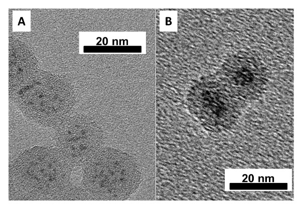
Figure 2: Representative TEM images of (A) multiply-coated WOx NPs within SiO2 spheres and (B) singly-coated Ta0.3W0.7Ox NPs within SiO2 spheres. The scale bars are in nanometers. Modified from reference 26.

Figure 3: Representative TEM images of SiO2/WOx synthesized under identical conditions described in the procedure except with 60 ml of Igepal® CO-520 instead of 54 ml of the Brij®-L4 surfactant. The scale bar is in nanometers. Modified from reference 26.

Figure 4: Representative PXRD diffractograms of SiO2/WOx coated at different pH values. Carburizations were conducted at 835 °C for 4 hr under 21% CH4/H2 and are shown for materials coated using a pH of (A) 10, (B) 10.5, (C) 10.9, and (D) 11.1. The low pH syntheses (A and B) have quartz-like silica (indicated by the sharp peak at 22°) and multiple carbide phases while the high pH syntheses (C and D) have a broad peak centered at 22°, indicative of amorphous silica, and single-phase face-centered-cubic WC NPs. Re-print with permission from reference 26.

Figure 5: Solvent precipitation effect studies by precipitating SiO2/WOx or SiO2/MoxW1-xOy with (A) Methanol, (B) Acetone, and (C) Isopropanol. All materials were rinsed with acetone after precipitation. The PXRD diffractograms are for the resulting materials post-carburization at 835 °C for 4 hr under 21% CH4/H2. Re-print with permission from reference 26.

Figure 6: Representative TEM and HAADF-STEM images of (A) 1-2 nm SiO2/WC NPs post-carburization, (B) 2-3 nm SiO2/WC NPs post-carburization, (C) 7-10 nm SiO2/WC NPs post-carburization, (D) 9-13 nm SiO2/WC NPs post-carburization. The scale bars are in nanometers. Modified from reference 26.

Figure 7: (A) photographs of a hexagonal WC nanodispersion dispersed in water at 7.5 mg/ml before and after three weeks of sitting in stagnant ambient conditions, (B) representative HAADF-STEM image of an unsupported β-WC nanopowder, (C) representative HAADF-STEM image of β-WC NPs supported on carbon black at 25 wt%. The scale bars are in nanometers. Modified from reference 26.

Figure 8: PXRD diffractograms of silica-encapsulated monometallic and heterometallic early transition metal carbides and nitrides of various sizes. All TMNs were nitridized under 100 sccm NH3 at 800 °C for 4 hr. 2-3 nm SiO2/W2C was synthesized at 775 °C under 18% CH4/H2 for 4 hr while all of the <3 nm TMC NPs were synthesized at 835 °C under 21% CH4/H2. The larger TMC NPs were synthesized at 900 °C under 21% CH4/H2. Modified from reference 26.
Subscription Required. Please recommend JoVE to your librarian.
Discussion
A procedure for synthesizing non-sintered, metal terminated transition metal carbide and nitride nanoparticles with tunable sizes and structure is presented here.26 Critical steps in the method include: using a moisture-free RBF to contain the diluted metal alkoxide precursor, avoiding alkali metal impurities during all steps, precipitating the RME with excess methanol as opposed to acetone or isopropanol, performing a proper leak check before carburizing or nitridizing the components, and using proper PPE when working with ammonium bifluoride.
The method can be modified in several areas. The TMO PSD can be adjusted using different RME systems, different water:surfactant ratios, different metal alkoxide:water ratios, different pH values, and different hydrolysis times. The TMCN PSD can be manipulated by manipulating the starting TMO PSD as well as by adding different amounts of NH4OH and TEOS, using different TEOS hydrolysis times, and using different carburization/nitridation temperatures. The crystalline phase-purity of the TMCN NPs can be manipulated using different temperatures and different centerline velocities of the carburizing/nitridizing gases. The composition of the TMCN NPs can be adjusted by using any hydrolysable early transition metal alkoxide, leading to a large array of potential multimetallic TMC and TMN NPs that could be synthesized with this method.
This technique is most suitable for applications of TMC and TMN NPs that require non-sintered particles of finely controlled sizes that also exhibit metal-terminated surfaces. This technique is also suitable for the ease with which a variety of multimetallic TMC and TMN NPs can be formulated. The technique is limited by the thermal stability of the silica coatings. TMC and TMN NPs that require carburization or nitridation temperatures in excess of 1,000 °C likely cannot be synthesized by this method due to the thermal collapse of the silica microporosity at these extreme temperatures. The technique is also limited to TMC and TMN NPs that are stable in either ammonium bifluoride or alkaline solutions as either an acidic or an alkaline treatment is required to remove the silica coatings after carburization/nitridation.
With respect to existing methods to synthesize TMCN NPs, this method is unique in its ability to simultaneously mitigate both particle sintering and excess surface impurity deposition. It is also unique in its versatility for synthesizing a wide array of monometallic and multimetallic TMCN NPs, requiring only that a hydrolysable early transition metal alkoxide precursor can be purchased or synthesized. Although this method is more complex than standard wet-impregnation syntheses, it allows non-sintered and metal-terminated TMCN NPs to be loaded onto a high surface area support at room temperature and at any desired wt% loading. In wet impregnation syntheses, the catalyst supports must be exposed to carburizing conditions, leading to their thermal degradation, and low wt% loadings must be used to mitigate excessive particle sintering.
Future directions after learning this technique include exploration of other multimetallic compositions, other RME or Sol-Gel systems, using ceramic coatings other than silica such as alumina, co-feeding carburization and nitridation gases, and using other reactive gas precursors to make for example borides or phosphides.
Subscription Required. Please recommend JoVE to your librarian.
Disclosures
The authors have nothing to disclose.
Acknowledgments
This work was sponsored by the Chemical Sciences, Geosciences and Biosciences Division, Office of Basic Energy Sciences, Office of Science, U.S. Department of Energy, grant no. DE-FG02-12ER16352. S.T.H. thanks the National Science Foundation for financial support through the National Science Foundation Graduate Research Fellowship under Grant No. 1122374.
Materials
| Name | Company | Catalog Number | Comments |
| n-heptane | Sigma-Aldrich | 246654 | |
| polyoxyethylene (4) lauryl ether | Sigma-Aldrich | 235989 | Brij® L4 |
| tungsten (VI) isopropoxide | Alfa Aesar | 40247 | W(VI)IPO |
| tungsten (VI) chloride | Sigma-Aldrich | 241911 | To prepare W(VI)IPO, homemade |
| tungsten (IV) chloride | Strem Chemicals | 74-2348 | To prepare W(IV)IPO, homemade |
| tantalum (V) isopropoxide | Alfa Aesar | 40038 | Ta(V)IPO |
| niobium (V) isopropoxide | Alfa Aesar | 36572 | Nb(V)IPO |
| nickel (II) methoxyethoxide | Alfa Aesar | 42377 | Ni(II)MEO |
| titanium (IV) isopropoxide | Sigma-Aldrich | 87560 | Ti(IV)IPO |
| molybdenum (V) isopropoxide | Alfa Aesar | 39159 | Mo(V)IPO |
| molybdenum (V) chloride | Sigma-Aldrich | 208353 | To prepare Mo(V)IPO, homemade |
| tetraethyl orthosilicate | Sigma-Aldrich | 333859 | TEOS |
| ammonium hydroxide | Sigma-Aldrich | 320145 | |
| methanol | Sigma-Aldrich | 34860 | |
| anhydrous isopropanol | Sigma-Aldrich | 278475 | To prepare homemade alkoxides |
| ammonium bifluoride | Sigma-Aldrich | 224820 | |
| carbon black | Cabot Corp. | Vulcan® XC72R | |
| Methane | AirGas | ME R300 | |
| Hydrogen | AirGas | HY UHP300 | |
| Ammonia | AirGas | AM AH80N705 | |
| Quartz Tube Furnace | MTI Corp. | OTF-1200X-S-UL |
References
- Oyama, S. T. The Chemistry of Transition Metal Carbides and Nitrides. , Blackie. (1996).
- Michalsky, R., Zhang, Y. -J., Medford, A. J., Peterson, A. A. Departures from the Adsorption Energy Scaling Relations for Metal Carbide Catalysts. J. Phys. Chem. C. 118 (24), 13026-13034 (2014).
- Kimmel, Y. C., Xu, X., Yu, W., Yang, X., Chen, J. G. Trends in Electrochemical Stability of Transition Metal Carbides and Their Potential Use As Supports for Low-Cost Electrocatalysts. ACS Catal. 4 (5), 1558-1562 (2014).
- Levy, R. B., Boudart, M. Platinum-like behavior of tungsten carbide in surface catalysis. Science. 181, 547-549 (1973).
- Chen, Z., Higgins, D., Yu, A., Zhang, L., Zhang, J. A review on non-precious metal electrocatalysts for PEM fuel cells. Energy Environ. Sci. 4 (9), 3167-3192 (2011).
- Esposito, D. V., Chen, J. G. Monolayer platinum supported on tungsten carbides as low-cost electrocatalysts: opportunities and limitations. Energy Environ. Sci. 4, 3900 (2011).
- Stottlemyer, A. L., Kelly, T. G., Meng, Q., Chen, J. G. Reactions of oxygen-containing molecules on transition metal carbides: Surface science insight into potential applications in catalysis and electrocatalysis. Surf. Sci. Rep. 67, 201-232 (2012).
- Bell, A. T. The impact of nanoscience on heterogeneous catalysis. Science. 299, 1688-1691 (2003).
- Kimmel, Y. C., Esposito, D. V., Birkmire, R. W., Chen, J. G. Effect of surface carbon on the hydrogen evolution reactivity of tungsten carbide (WC) and Pt-modified WC electrocatalysts. Int. J. Hydrogen Energy. 37, 3019-3024 (2012).
- Yang, X., Kimmel, Y. C., Fu, J., Koel, B. E., Chen, J. G. Activation of Tungsten Carbide Catalysts by Use of an Oxygen Plasma Pretreatment. ACS Catal. 2, 765-769 (2012).
- Garcia-Esparza, A. T., et al. Tungsten carbide nanoparticles as efficient cocatalysts for photocatalytic overall water splitting. ChemSusChem. 6, 168-181 (2013).
- Yan, Z., Cai, M., Shen, P. K. Nanosized tungsten carbide synthesized by a novel route at low temperature for high performance electrocatalysis. Sci. Rep. 3, 1646 (2013).
- Giordano, C., Erpen, C., Yao, W., Antonietti, M. Synthesis of Mo and W carbide and nitride nanoparticles via a simple 'urea glass' route. Nano Lett. 8, 4659-4663 (2008).
- Abdullaeva, Z., et al. High temperature stable WC1−x@C and TiC@C core–shell nanoparticles by pulsed plasma in liquid. R. Soc. Chem. Adv. 3, 513 (2013).
- Vallance, S. R., et al. Probing the microwave interaction mechanisms and reaction pathways in the energy-efficient, ultra-rapid synthesis of tungsten carbide. Green Chem. 14, 2184 (2012).
- Shen, P. K., Yin, S., Li, Z., Chen, C. Preparation and performance of nanosized tungsten carbides for electrocatalysis. Electrochim. Acta. 55, 7969-7974 (2010).
- Nikiforov, A. V., et al. WC as a non-platinum hydrogen evolution electrocatalyst for high temperature PEM water electrolysers. Int. J. Hydrogen Energy. 37, 18591-18597 (2012).
- Fang, Z. Z., Wang, X., Ryu, T., Hwang, K. S., Sohn, H. Y. Synthesis, sintering, and mechanical properties of nanocrystalline cemented tungsten carbide – A review. Int. J. Refract. Met. Hard Mater. 27, 288-299 (2009).
- Liu, Y., Kelly, T. G., Chen, J. G., Mustain, W. E. Metal Carbides as Alternative Electrocatalyst Supports. ACS Catal. 3, 1184-1194 (2013).
- Nie, M., Shen, P. K., Wei, Z. Nanocrystaline tungsten carbide supported Au–Pd electrocatalyst for oxygen reduction. J. Power Sources. 167 (1), 69-73 (2007).
- Ham, D. J., et al. Palladium-nickel alloys loaded on tungsten carbide as platinum-free anode electrocatalysts for polymer electrolyte membrane fuel cells. Chem Commun (Camb). 47 (20), 5792-5794 (2011).
- Yan, Y., et al. Template-free pseudomorphic synthesis of tungsten carbide nanorods. Small. 8, 3350-3356 (2012).
- Esposito, D. V., et al. Low-cost hydrogen-evolution catalysts based on monolayer platinum on tungsten monocarbide substrates. Angew. Chem. Int. Ed. 49, 9859-9862 (2010).
- Esposito, D. V., Hunt, S. T., Kimmel, Y. C., Chen, J. G. A new class of electrocatalysts for hydrogen production from water electrolysis: metal monolayers supported on low-cost transition metal carbides. J. Am. Chem. Soc. 134, 3025-3033 (2012).
- Kelly, T. G., Hunt, S. T., Esposito, D. V., Chen, J. G. Monolayer palladium supported on molybdenum and tungsten carbide substrates as low-cost hydrogen evolution reaction (HER) electrocatalysts. Int. J. Hydrogen Energy. 38, 5638-5644 (2013).
- Hunt, S. T., Nimmanwudipong, T., Roman-Leshkov, Y. Engineering non-sintered, metal-terminated tungsten carbide nanoparticles for catalysis. Angew. Chem. Int. Ed. Engl. 53 (20), 5131-5136 (2014).
- Mehrota, R. C. Alkoxides and Alkylalkoxides of Metals and Metalloids. Inorg. Chim. Acta. 1, 99-112 (1967).
- Munoz-Aguado, M., Gregorkiewitz, M. Sol-Gel Synthesis of Microporous Amorphous Silica from Purely Inorganic Precursors. J. Colloid Interface Sci. 185, 459-465 (1997).
