Presented here is a mild 3D printing technique driven by alternating viscous-inertial forces to enable the construction of hydrogel microcarriers. Homemade nozzles offer flexibility, allowing easy replacement for different materials and diameters. Cell binding microcarriers with a diameter of 50-500 µm can be obtained and collected for further culturing.
Method Article
3D Printing of In Vitro Hydrogel Microcarriers by Alternating Viscous-Inertial Force Jetting
* These authors contributed equally
In This Article
Summary
Abstract
Microcarriers are beads with a diameter of 60-250 µm and a large specific surface area, which are commonly used as carriers for large-scale cell cultures. Microcarrier culture technology has become one of the main techniques in cytological research and is commonly used in the field of large-scale cell expansion. Microcarriers have also been shown to play an increasingly important role in in vitro tissue engineering construction and clinical drug screening. Current methods for preparing microcarriers include microfluidic chips and inkjet printing, which often rely on complex flow channel design, an incompatible two-phase interface, and a fixed nozzle shape. These methods face the challenges of complex nozzle processing, inconvenient nozzle changes, and excessive extrusion forces when applied to multiple bioink. In this study, a 3D printing technique, called alternating viscous-inertial force jetting, was applied to enable the construction of hydrogel microcarriers with a diameter of 100-300 µm. Cells were subsequently seeded on microcarriers to form tissue engineering modules. Compared to existing methods, this method offers a free nozzle tip diameter, flexible nozzle switching, free control of printing parameters, and mild printing conditions for a wide range of bioactive materials.
Introduction
Microcarriers are beads with a diameter of 60-250 µm and a large specific surface area and are commonly used for large-scale culture of cells1,2. Their outer surface provides abundant growth sites for cells, and the interior provides a support structure for spatial proliferation. The spherical structure also provides convenience in monitoring and controlling parameters, including pH, O2, and concentration of nutrients and metabolites. When used in combination with stirred tank bioreactors, microcarriers can achieve higher cell densities in a relatively small volume compared to conventional cultures, thereby providing a cost-effective way to achieve large-scale cultures3. Microcarrier culture technology has become one of the main techniques in cytological research, and much progress has been made in the field of large-scale expansion of stem cells, hepatocytes, chondrocytes, fibroblasts, and other structures4. They have also been found to be ideal drug delivery vehicles and bottom-up units, therefore taking on an increasingly important role in clinical drug screening and in vitro tissue engineering repair5.
To meet mechanical property requirements in different scenarios, multiple types of hydrogel materials have been developed for use in the construction of microcarriers6,7,8,9,10,11. Alginate and hyaluronic acid (HA) hydrogels are two of the most used microcarrier materials owing to their good biocompatibility and crosslinkability12,13. Alginate can be easily cross-linked by calcium chloride, and its mechanical properties can be modulated by changing the cross-linking time. Tyramine-conjugated HA is cross-linked by the oxidative coupling of tyramine moieties catalyzed by hydrogen peroxide and horseradish peroxidase14. Collagen, due to its unique spiral structure and cross-linked fiber network, is often used as an adjuvant to mix into the microcarriers to further promote cell attachment15,16.
Current methods for preparing microcarriers include microfluidic chips, inkjet printing, and electrospray17,18,19,20,21,22,23. Microfluidic chips have been proven to be fast and efficient in producing uniform-sized microcarriers24. However, this technology relies on a complex flow channel design and fabrication process25. High temperature or excessive extrusion forces during inkjet printing, as well as intense electric fields in the electrospray approach, may adversely affect the properties of the material, especially its biological activity19. Besides, when applied to various biomaterials and diameters, the customized nozzles used in these methods result in limited processing complexity, high cost, and low flexibility.
To provide a convenient method for microcarrier preparation, a 3D printing technique called alternating viscous-inertial forces jetting (AVIFJ) has been applied to construct hydrogel microcarriers. The technique utilizes downward driving forces and static pressure generated during vertical vibration to overcome the surface tension of the nozzle tip and thus form droplets. Instead of severe forces and thermal conditions, small rapid displacements act directly on the nozzle during printing, causing a minor effect on the physicochemical properties of the bioink and presenting great attraction for bioactive materials. Utilizing the AVIFJ method, microcarriers of multiple biomaterials with diameters of 100-300 µm were successfully formed. Besides, the microcarriers were further proven to bind cells well and provide a suitable growth environment for adhered cells.
Protocol
1. Cell culture
- Supplement high-glucose Dulbecco's modified Minimum Essential Medium (H-DMEM) with 10% fetal bovine serum (FBS), 1% nonessential amino acid solution (NEAA), 1% penicillin G and streptomycin, and 1% Glutamine supplement as culture media for A549 cells.
- Culture A549 cells in a CO2 incubator at 37 °C and with 5% CO2
- Dissociate cells for subculture using trypsin at approximately 80% confluence.
- Use 3 mL of trypsin to treat the cells in the T75 culture flask at 37 °C for 3 min, and then add 6 mL of culture medium to stop the trypsinization.
- Pipette the culture medium to harvest loosely adhered cells.
- Centrifuge at 72.5 x g for 3 min. Remove the supernatant and resuspend with 3 mL of fresh medium.
- Transfer 1 mL of cell suspension to a new T75 culture flask containing 10 mL of fresh medium. Change the culture medium every 2 days.
2. Preparation of nozzles
- Load glass micropipettes onto the puller following the manufacturer's instructions. The outer diameter, inner diameter, and length of the micro-jet pipe are 1.5 mm, 1.1 mm, and 100 mm, respectively.
- Set the pulling parameters for the puller. Specifically, the values of HEAT, PULL, VELOCITY, TIME, and PRESSURE are set to 560, 255, 255, 150, and 500 by default, respectively. Pull off the nozzle under these parameters.
CAUTION: The nozzle obtained after pulling off is very sharp, and careless operation may cause injuries. - Cut off the resulting nozzle (step 2.2) at the designated diameter by a micro-forge device following the manufacturer's instructions to obtain a specific tip diameter. Specifically, locate the specified diameter of the nozzle onto the heated platinum wire. Heat the wire up to 60 °C for about 5 s and pull the nozzle apart.
- Immerse the printhead of the nozzle in a hydrophobic agent for 30 min, followed by three cycles of rinsing with sterilized water.
- Before printing, sterilize the nozzle in alcohol for 5 min and rinse it with sterilized water three times to remove the residual alcohol.
3. Preparation of hydrogel bioink
- Dissolve NaCl (0.45 g) into 50 mL of sterile water to obtain a 0.9% (w/v) NaCl solution. Vibrate the solution to promote dissolution. After being completely dissolved, filter the solution through a 0.45 µm polyethylene terephthalate filter membrane.
- Weigh low-viscosity sodium alginate powder (1 g) and dissolve it in 25 mL of NaCl solution (step 3.1) at a high temperature of 60-80 °C overnight to obtain a 4% (w/v) sodium alginate stock solution. The stock solution can be stored at 4 °C for 1 month.
- Sterilize the sodium alginate stock solution (step 3.2) by heating it three times in an oven (70 °C) for 30 min.
- Dilute proper volume of sodium alginate stock solution (step 3.3) in 0.9% NaCl solution (step 3.1) at concentrations of 2%, 1.5%, and 0.5% (w/v).
NOTE: In addition to heating in the oven, other preparation processes of sodium alginate solution should be carried out in the hood. - Dissolve 1 g of gelatin powder in 25 mL of NaCl solution (step 3.1) at a high temperature of 60-80 °C overnight to obtain a 4% (w/v) gelatin stock solution. The stock solution can be stored at 4 °C for 1 month.
- Sterilize the gelatin stock solution (step 3.5) by heating it three times in an oven (70 °C) for 30 min.
- Dilute the proper volume of gelatin stock solution (step 3.6) in 0.9% NaCl solution (step 3.1) at a concentration of 1.5% (w/v).
NOTE: In addition to heating in the oven, other preparation processes of gelatin solution should be carried out in the hood. - To promote cell binding on the microcarriers, prepare the alginate-collagen solution by mixing the 2% (w/v) sodium alginate solution and the Type I collagen solution from rat tail (4 mg/mL) at a ratio of 3:1. Adjust the solution to pH 7.2 with 0.1 M NaOH solution and use immediately after preparation.
- Dissolve the tyrosine-modified HA flocculent solid in phosphate buffer saline (PBS) solution at 60-80 °C overnight to obtain a 0.8% w/w tyrosine-modified hyaluronic acid PBS solution. The stock solution can be stored at 4 °C for 1 month.
- Sterilize the tyrosine-modified HA PBS solution by heating it three times in an oven (70 °C) for 30 min.
- Dissolve horseradish peroxidase powder (500 enzyme activity unit/mg) in PBS solution to obtain 8 enzyme activity unit/mg horseradish peroxidase PBS solution.
- Dilute hydrogen peroxide solution (30%, w/w) by DI water to 4 mM.
- Prepare the modified HA-horseradish peroxidase solution by mixing tyrosine-modified hyaluronic acid PBS solution and horseradish peroxidase PBS solution at a ratio of 1:1.
NOTE: In addition to heating in the oven, other preparation processes of HA-horseradish peroxidase solution should be carried out in the hood.
4. Microdroplets formation based on AVIFJ
- Use a home-established cell printing system as previously reported (Figure 1A)26. The electrical signal output by the waveform generator is first amplified and then drives piezoelectric ceramics to generate controllable deformation. The nozzle fixed on the piezoelectric ceramic thus produces controllable vibrations.
- Sterilize the printing system by wiping with 75% (v/v) alcohol and ultraviolet (UV) exposure overnight.
- Load 5 mL of bioink (step 3.1) into a disposable sterile syringe. Install the syringe on the syringe pump.
- Connect the syringe (step 4.3) and nozzle (step 2.5) with a silicone hose of 1 mm inner diameter.
- Fix the nozzle (step 4.4) to be used for printing by adjusting the tightness of the clamping screw. Keep the tip of the nozzle away from the substrate during installation to avoid damage and contamination.
CAUTION: If the nozzle is broken during installation, please wear thicker gloves and carefully clean up glass fragments and residues. - Rapidly push the syringe pump and load the bioink (step 4.3) to the nozzle (step 4.5). Set the flow rate at 30 µL/min. Wipe off the excess material at the tip.
- Set signal generator parameters. Import self-designed waveform containing 500,000 sampling points. Set the sampling rate and peak-to-peak voltage (Vpp) as 5 million samples/s and 10 V, respectively.
- Clean slides or Petri dishes with deionized water. Place them under the nozzle as the printing substrate.
- Preset the motion path and trigger mode of vibration as drop-on-demand.
- Print the droplets following the pre-designed patterns.
5. Microcarriers formation based on AVIFJ
- Repeat steps 4.1-4.4, except change the bioink to 2% (w/v) alginate solution (step 3.4), alginate-collagen solution (step 3.8), or modified HA-horseradish peroxidase solution (step 3.13).
- Dissolve 3 g of calcium chloride into 100 mL of sterile water to obtain 3% (w/v) calcium chloride solution. After being completely dissolved, filter the solution through a 0.45 µm polyethylene terephthalate filter membrane.
- Add 5 mL of cross-linking solution (calcium chloride solution or hydrogen peroxide solution) into a Petri dish. Place the Petri dish under the nozzle to work as a substrate.
- After printing, cross-link the microcarriers for 3 min.
- Collect microcarrier suspension in a centrifuge tube, and enrich microcarriers by centrifugation at 29 x g for 3 min. Resuspend the microcarriers in culture media at approximately 600 microcarriers/mL.
6. Inoculating cells on the surface of microcarriers
- Stain A549 cells with Cell Tracker Green CMFDA to facilitate the observation of cells. Specifically, remove culture media, add 5 mL of serum-free medium containing 10 µM Cell Tracker dye, and incubate cells for 30 min in an incubator. Then, replace the dye solution with fresh medium.
- Resuspend the A549 cell suspension at the density of 1.6 x 10⁶ cells/mL.
- Add 1 mL of alginate-collagen microcarrier suspension (step 5.3) and 1 mL of A549 cell suspension (step 6.1) into a low-adherent 6-well culture plate.
- Place the plate onto a shaker at 30 rpm in an incubator at 37 °C and 5% CO2.
- Take the plate off the shaker and wait for 30 min to let the microcarriers settle down. Half change the culture medium every 2 days.
7. Analysis of microdroplets/microcarriers formation
- Observe and measure the nozzle (step 2.2), the Petri dishes (step 4.10 and step 5.4), and cells with microcarriers (step 6.5) under a bright field microscope or confocal microscope. Specifically, the objective magnification is 4x, 10x, or 20x and the eyepiece magnification is 10x.
- Measure the diameter of the microcarriers by ImageJ software. According to the scale bar that comes with the microscope when shooting in the picture, set the actual size of the scale in ImageJ, and draw 10 lines of the radius or semi-major axis of the microcarriers. ImageJ can get the average size and standard deviation of these line segments.
Results
Printheads of varied convergence rates and diameters were fabricated to achieve the printing of multiple types of materials. The nozzles obtained with increasing pull strength are shown in Figure 1B. The nozzles were divided into three areas: reservoir (III), contraction (II), and printhead (I). The reservoir was the unprocessed part of the nozzle, in which the liquid provided static pressure and bioink input for printing. The contraction area was the main part for generating downward driving forces. The pull strength had a significant effect on the printhead, demonstrating a lower convergence rate with extended pull strength. The narrower and longer printhead increased the surface tension during printing, making the formation of discrete microdroplets more difficult, but facilitated the cutting of smaller-diameter tips in subsequent operations. Afterward, with the needle forging instrument, the printhead was cut off at the designated diameter (Figure 1C). Tips with various diameters, including 100, 120, 150, and 200 µm, were available to generate microcarriers of different sizes, meeting the requirements of various in vitro microtissues.
The stability and controllability of the printing process were first verified by printing droplets onto Petri dishes. With a 30 µm tip nozzle, multiple bioink, including PBS, 1.5% alginate, and 1.5% gelatin were stably printed (Figure 2A,B). The difficulty of printing a certain bioink was reflected in the sampling rate and Vpp used for printing. Low viscosity bioink such as NaCl solution were printed at smaller parameters, resulting in smaller droplet diameters. With increasing viscosity, the printing process became correspondingly more difficult, as the greater drive forces were needed and larger droplets would obtain (Figure 2B). With this mechanism, the adjustment of parameters and drive forces for a given bioink can be used to adjust different droplet sizes, as shown in Figure 2C. Figure 2D shows the arrangement of droplets forming the specific letters "THU" on a flat surface. Besides, the combination of microscopic observations allowed for the localization of microdroplets at smaller scales within 100 µm.
Alginate microcarriers (Figure 3A) and HA microcarriers (Figure 3C) were printed with tips of different diameters. The effects of the tip diameter on the alginate microcarrier diameter are shown in Figure 3B. Limited by the blockage caused by the volatilization of the solution when the size is too small, the smallest diameter of the printed alginate microcarriers was approximately 100 µm. While the largest diameter could reach up to 300 µm. The diameter of the printed microcarriers increases in line with the tip diameter and is always larger than the latter. When the diameter of the tip is larger than 250 µm, the bioink cannot be printed out. The diameter of printed modified HA microcarriers was 76.7 ± 1.8 µm with tip diameters of 75 µm (Figure 3C).
A549 cells and alginate-collagen microcarriers were seeded in a plate and placed on a shaker in the incubator. The cells were observed to adhere to the alginate-collagen microcarriers after mixing for 2 days. Cells progressively cover larger surface of microcarriers by proliferation. After cultivation for 6 days, A549 cells almost fully covered the microcarrier surfaces. This result confirms that the developed microcarriers can bind cells well and provide a suitable growth environment for the cells. Bright field images and confocal images of A549 cells adhering and proliferating on the surface of the microcarriers are shown in Figure 4.
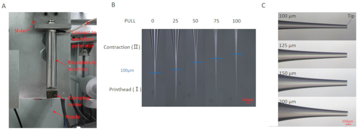
Figure 1: The AVIFJ printing system and the preparation of nozzles of various diameters. (A) The installation of AVIFJ nozzle. (B) Under specific PULL parameters, the printhead of the nozzle was shaped to converge at different rates. Scale bar: 200 μm. (C) With the needle forging instrument, the tip was cut off at designated positions. Scale bar: 200 μm. Please click here to view a larger version of this figure.
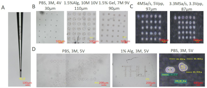
Figure 2: Printing of multiple types of biomaterials at various concentrations by AVIFJ. (A) The nozzle used in this section of results. The diameter of the tip was 30 μm. Scale bar: 100 μm. (B) Printing of multiple types of hydrogel materials including PBS, 1.5% alginate, and 1.5% gelatin at various parameters. M: a million samples per second, reflecting the duration of a single vibration. V: peak-to-peak voltage, reflecting the stroke of a single vibration. Scale bar: 100 μm. (C) The printing of 0.5% alginate at various parameters. Scale bar: 100 μm. (D) 2D arrangements and close positioning of droplets. Scale bar: 200 μm. Please click here to view a larger version of this figure.
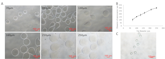
Figure 3: Microcarriers printed with different diameters of the nozzle tip. (A) 2% alginate microcarriers, printed with nozzle tip diameters at 70, 100, 130, 160, 210, and 250 μm, respectively. Scale bar: 100 μm. (B) Effect of the nozzle tip diameter on the size of microcarriers. The sizes of the microcarriers printed with nozzles of different diameters were statistically analyzed using ImageJ software. Ten microcarriers for each nozzle were selected and calculated. Data are presented as mean ± s.d. (C) Printed modified HA microcarriers with tip diameters at 75 μm. Scale bar: 100 μm. Please click here to view a larger version of this figure.
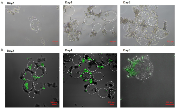
Figure 4: Seeding cells on alginate-collagen microcarriers. (A) Bright field images of A549 cells adhering and proliferating on the surface of the microcarriers. Scale bar: 100 μm. (B) Confocal images of A549 cells adhering and proliferating on the surface of the microcarriers. Scale bar: 100 μm. Dotted ellipses are used to highlight the border of microcarriers. Please click here to view a larger version of this figure.
Discussion
The protocol described here provides instructions for the preparation of multi-types of hydrogel microcarriers and subsequent cell seeding. Compared to microfluidic chip and inkjet printing methods, AVIFJ approach to constructing microcarriers offers greater flexibility and biocompatibility. An independent nozzle enables a wide range of lightweight nozzles, including glass micropipettes, to be used in these printing systems. The highly controllable processing enables parameters including the volume of the reservoir, the inner diameter, and the shape of the printhead to be freely adjusted. Furthermore, the disposable nozzle facilitates sterilization for switching among multiple materials, which avoids potential contamination from repeated use. Finally, small and rapid displacements, instead of severe forces and thermal conditions, act directly on the nozzle during the printing process, maintaining the original physical and chemical properties of the printed bioink to the maximum extent; this feature is highly attractive for biomaterial applications.
The most critical steps for successful production of microcarriers of the correct size are: 1) Preparing nozzles with tips of appropriate diameters, and 2) adapting the suitable sampling rate and Vpp according to the viscosity of the printed bioink. The stability of microcarrier construction is further achieved by removing satellite droplets and applying external driving forces. The increased parameters facilitate the formation of microcarriers, but excessive driving forces are the key reason for satellite microcarrier formation, resulting in an inhomogeneous microcarrier size. Thus, to improve the uniformity of the microcarrier size, it is recommended to use appropriate (not excessive) sampling rates and Vpp. Another aspect for improving microcarrier stability is the application of external driving forces. The external driving forces complement the static pressure and downward driving forces, working together to overcome the surface tension at the tip. A syringe pump pushing was experimented with to feed the nozzle and supplementary additional pushing forces. Specifically, the nozzle was connected to a syringe, whose pushing speed was adjusted by a precision syringe pump. This method allowed the same concentration of hydrogel solution to form microdroplets at limited parameters, which is beneficial for reducing the size of the microcarriers. Other studies have reported the use of electrostatic fields or squeezing reservoirs to promote microdroplet printing27,28.
Although applying external driving forces is expected to broaden the range of types and concentrations of printable inks, the printing technique used here still faces the challenge of limited driving forces and is still ineffective for high-viscosity inks.
The feasibility of microcarrier preparation and cell adhesion using an AVIFJ 3D printer was preliminarily verified. Subsequent work will focus on the potential applications of the microcarriers in the construction of biological models. In future research, the cell adhesion process will be optimized so that the number and types of cells will be further increased and enriched, which is expected to form a functional tissue or vascular network. Besides, bioink will be further co-printed with cells to form functional heterogeneous structural units. Microcapsules, microparticles, and other structures can also be loaded inside the microcarriers to form a sustained drug release model for clinical use. In summary, a method has been developed for constructing tissue micro-units, which are expected to be scaled up to form in vitro functional micro-tissues.
Disclosures
The authors have nothing to disclose.
Acknowledgements
This work was supported by the Beijing Natural Science Foundation (3212007), Tsinghua University Initiative Scientific Research Program (20197050024), Tsinghua University Spring Breeze Fund (20201080760), the National Natural Science Foundation of China (51805294), National Key Research and Development Program of China (2018YFA0703004), and the 111 Project (B17026).
Materials
| Name | Company | Catalog Number | Comments |
|---|---|---|---|
| A549 cells | ATCC | CCL-185 | Human non-small cell lung cancer cell line |
| Bright field microscope | Olympus | DP70 | |
| Confocal microscope | Nikon | TI-FL | |
| Fetal bovine serum, FBS | BI | 04-001-1ACS | |
| Gelatin | SIGMA | G1890 | |
| Glass micropipettes | sutter instrument | b150-110-10 | |
| GlutaMAX | GIBCO | 35050-061 | |
| H-DMEM | GIBCO | 11960-044 | Dulbecco's modified eagle medium |
| Horseradish peroxidase powder | SIGMA | P6782 | |
| Hydrophobic agent | 3M | PN7026 | Follow the manufacturer's instructions and use after dilution |
| Micro-forge device | narishige | MF-900 | |
| Non-essential amino acids, NEAA | GIBCO | 11140-050 | non-essential amino acids |
| Penicillin G and streptomycin | GIBCO | 15140-122 | |
| Petri dish | SIGMA | P5731-500EA | |
| Puller | sutter instrument | P-1000 | |
| Sodium alginate | SIGMA | A0682 | |
| Trypsin | GIBCO | 25200-056 | |
| Type I collagen solution from rat tail | SIGMA | C3867 |
References
- Chen, A. K., Reuveny, S., Oh, S. K. W. Application of human mesenchymal and pluripotent stem cell microcarrier cultures in cellular therapy: Achievements and future direction. Biotechnol Advances. 31, 1032-1046 (2013).
- Li, B., et al. Past, present, and future of microcarrier-based tissue engineering. Journal of Orthopaedic Translation. 3, 51-57 (2015).
- Badenes, S. M., Fernandes, T. G., Rodrigues, C. A. V., Diogo, M. M., Cabral, J. M. S. Microcarrier-based platforms for in vitro expansion and differentiation of human pluripotent stem cells in bioreactor culture systems. Journal of Biotechnol. 234, 71-82 (2016).
- de Soure, A. M., Fernandes-Platzgummer, A., Da Silva, C. L., Cabral, J. M. S. Scalable microcarrier-based manufacturing of mesenchymal stem/stromal cells. Journal of Biotechnol. 236, 88-109 (2016).
- Naqvi, S. M., et al. Living cell factories - electrosprayed microcapsules and microcarriers for minimally invasive delivery. Advanced Materials. 28, 5662-5671 (2016).
- Sarkar, S., et al. Chitosan: A promising therapeutic agent and effective drug delivery system in managing diabetes mellitus. Carbohydrate Polymers. 247, (2020).
- Sulaiman, S. B., Idrus, R. B. H., Hwei, N. M. Gelatin microsphere for cartilage tissue engineering: current and future strategies. Polymers. 12, (2020).
- Huang, L., Abdalla, A. M. E., Xiao, L., Yang, G. Biopolymer-based microcarriers for three-dimensional cell culture and engineered tissue formation. International Journal of Molecular Sciences. 21, (2020).
- Isiklan, N., Tokmak, S. Development of thermo/pH-responsive chitosan coated pectin-graft-poly(N, N-diethyl acrylamide) microcarriers. Carbohydrate Polymers. 218, 112-125 (2019).
- Lau, T. T., Wang, C., Wang, D. A. Cell delivery with genipin crosslinked gelatin microspheres in hydrogel/microcarrier composite. Composites Science & Technology. 70, 1909-1914 (2010).
- Lau, T. T. Hydrogel-microcarrier composite systems for cell delivery in tissue engineering. Acta Biomaterialia. 10, 1646-1662 (2014).
- Kwon, Y. J., Peng, C. A. Calcium-alginate gel bead cross-linked with gelatin as microcarrier for anchorage-dependent cell culture. Biotechniques. 33, 218(2002).
- Leach, J. B., Bivens, K. A., Patrick, C. W., Schmidt, C. E. Photocrosslinked hyaluronic acid hydrogels: natural, biodegradable tissue engineering scaffolds. Biotechnology & Bioengineering. 82, 578-589 (2003).
- Kurisawa, M., Chung, J. E., Yang, Y. Y., Gao, S. J., Uyama, H. Injectable biodegradable hydrogels composed of hyaluronic acid-tyramine conjugates for drug delivery and tissue engineering. Chemical Communications. 34, 4312-4314 (2005).
- Yao, R., Alkhawtani, A. Y. F., Chen, R., Luan, J., Xu, M. Rapid and efficient in vivo angiogenesis directed by electro-assisted bioprinting of alginate/collagen microspheres with human umbilical vein endothelial cell coating layer. International Journal of Bioprinting. 5, 194(2019).
- Mahou, R., Vlahos, A. E., Shulman, A., Sefton, M. V. Interpenetrating alginate-collagen polymer network microspheres for modular tissue engineering. Acs Biomaterials Science & Engineering. 4 (11), 3704-3712 (2017).
- Aftab, A., et al. Microfluidic platform for encapsulation of plant extract in chitosan microcarriers embedding silver nanoparticles for breast cancer cells. Applied Nanoscience. 10, 2281-2293 (2020).
- Park, W., et al. Microfluidic-printed microcarrier for in vitro expansion of adherent stem cells in 3D culture platform. Macromolecular Bioscience. 19, (2019).
- Chui, C., et al. Electrosprayed genipin cross-linked alginate-chitosan microcarriers for ex vivo expansion of mesenchymal stem cells. Journal of Biomedical Materials Research Part A. 107, 122-133 (2019).
- Min, N. G., Ku, M., Yang, J., Kim, S. Microfluidic production of uniform microcarriers with multicompartments through phase separation in emulsion drops. Chemistry of Materials. 28 (5), 1430-1438 (2016).
- Park, W., Jang, S., Kim, T. W., Bae, J., Lee, E. A. Microfluidic-printed microcarrier for in vitro expansion of adherent stem cells in 3D culture platform. Macromolecular Bioscience. 19, (2019).
- Xu, T., Kincaid, H., Atala, A., Yoo, J. J. High-Throughput Production of Single-Cell Microparticles Using an Inkjet Printing Technology. Journal of Manufacturing Science & Engineering. 130, 137-139 (2008).
- Rao, W., et al. Enhanced enrichment of prostate cancer stem-like cells with miniaturized 3D culture in liquid core-hydrogel shell microcapsules. Biomaterials. 27 (27), 7762-7773 (2014).
- Choi, C. H., Weitz, D. A., Lee, C. S. One step formation of controllable complex emulsions: From functional particles to simultaneous encapsulation of hydrophilic and hydrophobic agents into desired position. Advanced Materials. 25, 2536-2541 (2013).
- Choi, A., Seo, K. D., Kim, D. W., Kim, B. C., Dong, S. K. Recent advances in engineering microparticles and their nascent utilization in biomedical delivery and diagnostic applications. Lab On A Chip. 17 (4), 591-613 (2017).
- Liu, T., Pang, Y., Zhou, Z., Yao, R., Sun, W. An integrated cell printing system for the construction of heterogeneous tissue models. Acta Biomaterialia. 95, 245-257 (2019).
- Hassan, K., et al. Functional inks and extrusion-based 3D printing of 2D materials: a review of current research and applications. NANOSCALE. 12, 19007-19042 (2020).
- Vithani, K., et al. An overview of 3D printing technologies for soft materials and potential opportunities for lipid-based drug delivery systems. Pharmaceutical Research. 36, (2019).
Reprints and Permissions
